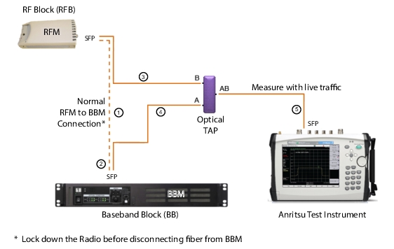
1. Lock down the RFM before disconnecting the fiber optic cable.
2. Disconnect the fiber cable from the BBM.
3. Connect the RFM to Port B on the optical TAP.
4. Connect a 3‑meter LC/LC Duplex Jumper from Port A on the optical TAP to the BBM.
5. Use a compatible SFP transceiver and Simplex fiber cable to connect the Anritsu test instrument to Port AB on the optical TAP.
Port A Out from Port AB is the downlink BBM signal.
Port B Out from Port AB is the uplink RFM signal.
6. If your test instrument has dual SFP ports, you can optionally connect it to another RFM, using the second port.
7. When all connections are complete, unlock the RFM.
8. Perform measurements using live traffic.
Connecting OBSAI Link to Anritsu Test Instrument
Warning
Laser radiation may be present at fiber optic cable connectors and ports. This laser radiation could present a nominal ocular hazard from either direct viewing or by diffuse reflection. Do not view the emitted laser radiation directly or indirectly because permanent blindness may result.