The Universal Serial Bus (USB) architecture is a high-performance networking standard that is considered “plug and play” compatible. The USB driver software is automatically detected and configured by the operating system of the devices that are connected to the bus. The instrument conforms to the USB 2.0 standard and is a USB “full‑speed” device that supports data rates of up to 10 Mbps with the following restrictions:
• One USB network can support up to 127 devices.
• The maximum length of USB cables between active devices is 5 meters for USB 2.0 and 3 meters for USB 1.0.
You must have NI‑VISA 2.5 or later installed on the controller PC and you must select the VISA library (visa32.dll) as a reference in a Visual Basic project. For remote USB control, the controlling PC must have a version of VISA installed that supports USBTMC (USB Test and Measurement Class) devices.
The USB 2.0 Mini‑B device connector can be used to connect the instrument directly to a PC. The first time the instrument is connected to a PC, the normal USB device detection by the computer operating system takes place.
1. Power on the instrument and controller PC and wait for the systems to power up completely.
2. Connect the USB cable Mini‑B connector to the instrument.
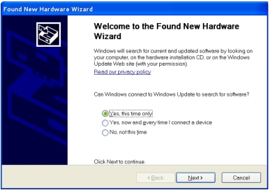
3. Connect the USB cable A connector to the controller PC USB host port. The controller PC should indicate “New Hardware Found” if the combination of USB VID/PID/Serial Number has never been connected to this controller PC.
Found New Hardware Wizard
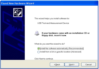
4. Select to allow the Wizard to search for and install the USB software automatically.
Found New Hardware Wizard
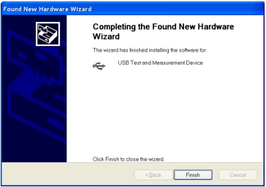
5. After the software finishes installing, close the Wizard by clicking Finish.