The instrument can measure CDMA performance over the air with an antenna, or by connecting the base station directly.
To measure a CDMA signal over the air, connect the appropriate frequency band antenna to the instrument’s RF Input connector and connect a GPS antenna to the GPS connector.
To connect the base station to the instrument, connect the power amplifier of the base station to the RF In port of the instrument using a coupler or attenuator.
|
The maximum input damage level of the RF In port is +30 dBm. To prevent damage always use a coupler or high power attenuator.
|
The instrument needs a timing reference in order to determine PN Offset and timing errors. This reference comes from the base station when it is connected, or it can be recovered from GPS when a GPS antenna is connected. The setup for this function is:
|
1.
|
Press the Setup main menu key.
|
|
2.
|
|
3.
|
 |
|
4.
|
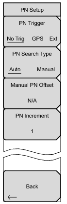
Press the PN Search Type submenu key to toggle between Auto or Manual. In Auto mode, the instrument automatically detects the strongest pilot, while in Manual mode it searches only for the specified PN.
|
|
5.
|
Press Back to return to the previous menu.
|
Walsh Codes setup is used to select whether cdmaOne (Walsh Codes 64) or CDMA2000 1xRTT (Walsh Codes 128) is required for the measurements. When 128 codes is selected, the upper CDP (Code Domain Power) graph displays the CDP in bit-reversed order.
|
1.
|
Press the Setup main menu key.
|
|
2.
|
Press the Walsh Codes submenu key, and the key is toggled between 64 codes and 128 codes.
|
 |
GPS Setup
GPS provides improved accuracy in the timing circuit, which reduces frequency error. To configure GPS, use the following procedure:
|
•
|
Install a GPS antenna to the GPS antenna connection on the instrument’s connector panel.
|
|
A DC voltage is present on the GPS connector. Never connect anything other than a GPS antenna to this port.
|
|
CDMA base stations have GPS available at the cell Site. Connect the instrument to the base station GPS connector to make accurate frequency error and timing measurements.
|