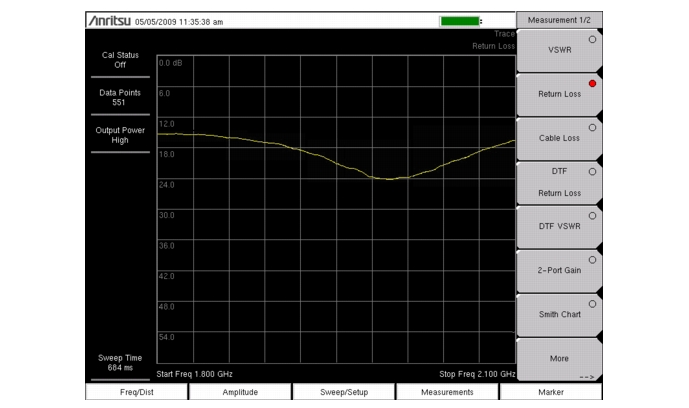
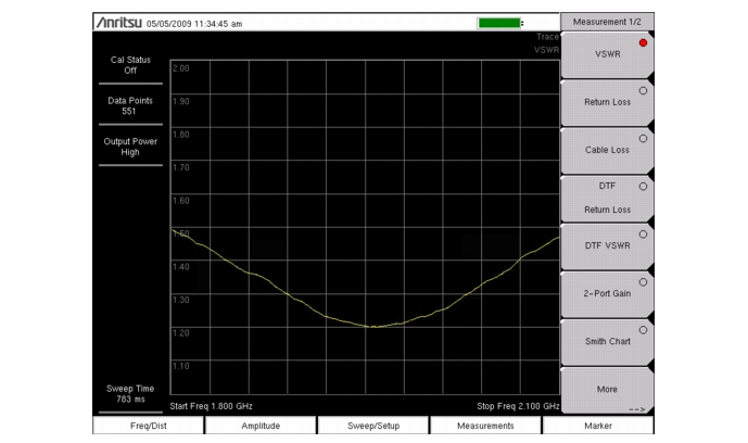
Return Loss is used to characterize RF components and systems. The Return Loss indicates how well the system is matched by taking the ratio of the reflected signal to the incident signal, measuring the reflected power in dB. The 1-port Measurement data can also be displayed linearly as VSWR, or by using Master Software Tools to display the reflection coefficient.
|
1.
|
If a test port extension cable is to be used, connect it to the RF Out connector.
|
|
2.
|
|
3.
|
Under the Freq/Dist main menu key, use the Start Freq and Stop Freq submenu keys to set the Start and Stop frequencies. Or enter a known signal standard by pressing Signal Standard submenu key followed by Select Standard (Figure: “Signal Standards”).
|
 |
|
4.
|
Press the Start Cal submenu key and perform a 1-port OSL calibration at the connector or at end of the extension cable. When the Calibration is finished, Cal Status On should be displayed in the upper left part of the display and the trace should be centered around 0 dB when the short or open is connected.
|
|
7.
|
 |
 |