The DTF measurement displays return loss (or VSWR) values versus distance. If the frequency measurements fail or indicate a problem in the system, then the DTF measurement can be used to identify and pinpoint the exact location of the problem. The DTF measurement shows the return loss value of all the individual components including connector pairs and cable components.
To measure the distance of a cable, DTF measurements can be made with an open or a short connected at the end of the cable. The peak indicating the end of the cable should be between 0 dB and 5 dB.
An open or short should not be used when DTF is used for troubleshooting because the open/short will reflect everything and the true value of a connector might be misinterpreted and a good connector could look like a failing connector.
A 50Ω load is the best termination for troubleshooting DTF problems because it will be 50Ω over the entire frequency range. The antenna can also be used as a terminating device but the impedance of the antenna will change over different frequencies because most antennas are only designed to have 15 dB or better return loss in the passband of the antenna.
DTF measurement is a frequency domain measurement and the data is transformed to the time domain using mathematics. The distance information is obtained by analyzing how much the phase is changing when the system is swept in the frequency domain.
Frequency selective devices such as TMAs (Tower Mounted Amplifiers), duplexers, filters, and quarter wave lightning arrestors change the phase information (distance information) if they are not swept over the correct frequencies. Care needs to be taken when setting up the frequency range whenever a TMA is present in the path. “Tower Mounted Amplifiers” provides TMA details.
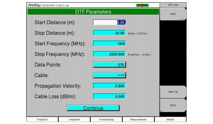
Because of the nature of the measurement, maximum distance range and fault resolution is dependent on the frequency range and number of data points. DTF Aid shows how the parameters are related. If the cable is longer than DMax, the only way to improve the horizontal range is to reduce the frequency span or to increase the number of data points. Similarly, the fault resolution is inversely proportional to the frequency range and the only way to improve the fault resolution is to widen the frequency span.
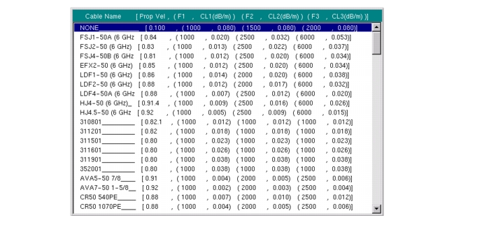
The BTS Master is equipped with a cable list (Figure: “Cable List”) including most of the common cables used today. Once the correct cable has been selected, the measurement parameters will update the propagation velocity and the cable attenuation values to correspond with the cable. These values can also be entered manually. Custom Cable lists can also be created with Master Software Tools and uploaded into the instrument. Incorrect propagation velocity values will affect the distance accuracy and inaccurate cable attenuation values will affect the accuracy of the magnitude value.
 |
Fault resolution is the system's ability to separate two closely spaced discontinuities. If the fault resolution is 10 feet and there are two faults 5 feet apart, the instrument will not be able to show both faults unless Fault Resolution is improved by widening the frequency span.
DMax is the maximum horizontal distance that can be analyzed. The Stop Distance can not exceed Dmax. If the cable is longer than Dmax, Dmax needs to be improved by increasing the number of data points or lowering the frequency span (ΔF). Note that the data points can be set to 137, 275, 551, 1102, or 2204
DTF Setup
|
1.
|
|
2.
|
Press the Freq/Dist main menu key.
|
|
3.
|
Press the Units submenu key and select m to display distance in meters or ft to display distance in feet.
|
|
4.
|
Press DTF Aid and use the touch screen, or arrow keys to navigate through all the DTF parameters.
|
|
a.
|
|
c.
|
|
d.
|
Press Continue.
|
|
5.
|
|
6.
|
|
7.
|
|
8.
|
 |