|
1.
|
|
2.
|
Press the Meas Mode submenu key to open the Select Meas Mode list, and then choose either Single or Continuous measurement.
|
|
3.
|
Press the Detect Parameter submenu key to automatically detect for Mode, GI and TMCC Information from the input signal.
|
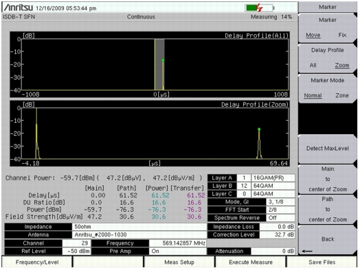
Press the Delay Profile submenu key to view the Delay Profile measurement screen. Press the More submenu key to display the “Meas Setup (2/2) (Delay Profile) Menu” and continue configuring the Delay Profile parameters.
|
1.
|
Press the Mode, GI submenu key, then highlight the desired Mode, Guard Interval parameter in the Select Mode, GI list. Then press Enter.
|
|
2.
|
Press the TMCC Information submenu key. The TMCC Information Editor dialog box and “TMCC Information Menu” are displayed.
|
|
a.
|
Set up the Layer Segments. The total sum of segments among segments A, B, and C must add up to 13.
|
|
c.
|
Use the Up/Down arrow keys or the rotary knob to change the segment number.
|
|
d.
|
Press the desired Layer Modulation submenu key (Layer A, Layer B, or Layer C) to set up the Layer Modulations.
|
|
e.
|
Press the Layer (A, B, or C) submenu key to scroll to the desired modulation: 64QAM, 16QAM, or QSPK.
|
|
f.
|
|
3.
|
Press the FFT Start submenu key to open the Select FFT Start list box, then select the desired start position with a guard interval (0/8 indicates no guard interval).
|
|
4.
|
Press the Spectrum Reverse submenu key to toggle between On and Off. The active state is underlined.
|
|
5.
|
|
a.
|
Press the Antenna (Correction Level) submenu key, highlight the desired Anritsu antenna model number, and then press Enter.
|
|
b.
|
|
c.
|
If you select Other, then the Impedance Loss submenu key is displayed in the Correction Value menu. Press the Impedance Loss submenu key to open the Impedance Loss Editor dialog box and enter a dB loss level within the displayed range.
|
|
d.
|
|
6.
|
Press the Delay Profile Vertical Range submenu key to display the “Delay Profile Vertical Range Menu”. Press the desired vertical range (dB) value submenu key. The red dot on the submenu key denotes the selected vertical range. Then press the Back submenu key to return to the “Meas Setup (2/2) (Delay Profile) Menu”.
|
|
7.
|
Press the Display Waveform submenu key to display the “Display Waveform Menu”. Press the appropriate submenu key to turn On or Off the following parameters:
|
|
a.
|
Press the Last Result submenu key to toggle it to On in order to view the last waveform (yellow) result.
|
|
b.
|
Press the Power Method submenu key to toggle it to On in order to display the delay path profile waveform (light blue) that is created by the power spectrum method.
|
|
c.
|
Press the Transfer Method submenu key to toggle it to On in order to display the delay path profile waveform (magenta) that is created by the transfer function method.
|
|
d.
|
|
8.
|
|
9.
|
|
a.
|
|
b.
|
Press the Delay Profile submenu key to select and configure the marker in the Delay Profile (All) view or Delay Profile (Zoom) view.
|
|
c.
|
If Delay Profile (Zoom) is selected, then press the Marker Mode submenu key to select either Normal or Zone.
|
|
d.
|
|
e.
|
|
f.
|
|
g.
|
Press the Inband Spectrum submenu key to view the Inband Spectrum measurement screen. Press the More submenu key to display the “Meas Setup (2/2) (Inband Spectrum) Menu”Meas Setup (2/2) menu and continue configuring the Inband Spectrum parameters.
|
1.
|
Press the Mode, GI submenu key. Highlight the desired Mode, Guard Interval parameter in the Select Mode, GI list, and then press Enter.
|
|
2.
|
Press the TMCC Information submenu key. The TMCC Information Editor dialog box and TMCC Information menu are displayed.
|
|
a.
|
Set up the Layer segment. The total sum of segments among segments A, B, and C must add up to 13.
|
|
b.
|
|
c.
|
Use the Up/Down arrow keys or the rotary knob to change the segment number.
|
|
e.
|
|
f.
|
Press the specific Layer Modulation submenu key to scroll to the desired modulation: 64QAM, 16QAM, or QSPK.
|
|
g.
|
|
3.
|
Press the FFT Start submenu key to open the Select FFT Start list box, and then select the desired start position with a guard interval (0/8 indicates no guard interval).
|
|
4.
|
Press the Spectrum Reverse submenu key to toggle between On and Off. The active state is underlined.
|
|
5.
|
|
a.
|
Press the Antenna (Correction Level) submenu key, highlight the desired Anritsu antenna model number in the Select Antenna list, and then press Enter.
|
|
b.
|
|
c.
|
If you select Other, then the Impedance Loss submenu key is displayed in the Correction Value menu. Press the Impedance Loss submenu key to open the Impedance Loss Editor dialog box and enter a dB loss level within the displayed range.
|
|
d.
|
|
6.
|
Press the Inband Spectrum Vertical Range submenu key to display the “Inband Spectrum Vertical Range Menu”. Select a range (dB). The red dot on the submenu key denotes the selected vertical range. Press the Back submenu key to return to the “Meas Setup (2/2) (Inband Spectrum) Menu”.
|
|
7.
|
|
8.
|
Press the Marker submenu key to display the “Marker Menu (Inband Spectrum)”Marker menu (refer to Figure: “Marker Menu (Inband Spectrum)”). (Use the arrow keys or rotary knob to move the marker and delta marker.)
|
|
a.
|
|
b.
|
|
c.
|
Press the Execute Measure main menu key to begin testing. If the input signal cannot be measured, then a message is displayed with red highlighting near the top of the display area, as follows:
 |
Press the Save Files main menu key to save a measurement. A confirmation window opens briefly to indicate that the measurement has been saved.
Measurement files are stored automatically or manually. Pressing the Save Files main menu key creates a title for the measurement file and stores the file into the instrument memory. Manually saving a file requires multiple steps for naming the file before storing into the instrument memory.
Files are saved in the JPEG format and the CSV format. The filename format uses a string of 3 characters followed by a string of digits for the date and time. The entire character string appears as follows:
The date is expressed as year (YYYY), month (MM), and day (DD) followed by an underscore, and then the time is expressed as hour (HH), minute (MM), and second (SS), all followed by a period and then the file extension (CSV or JPG).