Before powering on the PIM Master or the connected Anritsu handheld instrument, connect the cables between the instruments and the DUT as shown in the diagram in Figure: “PIM Master Connection Diagram”. A connection diagram is also printed on the MW8219A PIM Master connection panel.
|
In most cases, information and parameters can be entered through the keypad, the directional arrows, or the rotary knob. The numerical keypad enters the information directly. The up and down arrow keys change a frequency parameter by 1 MHz. The left and right arrow keys change the frequency parameter by 10 MHz. The rotary knob changes the frequency parameter by 1 MHz. Choose whichever method is most convenient to enter the required information. Refer to your Anritsu handheld instrument User Guide for additional information.
|
A cable harness is part of the standard accessories included with the PIM Master to connect to an Anritsu handheld instrument. Use this cable harness to make the following connections:
|
1.
|
Connect the USB cable between the USB Type-B receptacle connector of the PIM Master and the Type-A USB receptacle connector of the handheld instrument.
|
|
2.
|
Connect the N-Type cable between the RF Out connector of the PIM Master to the RF In connector of the handheld instrument.
|
|
3.
|
Connect the BNC cable between the 10MHz-OUT BNC connector of the PIM Master to the Ref In BNC connector of the handheld instrument.
|
|
4.
|
Connect the Test Port Cable between the Test Port connector of the PIM Master to the Device under test (DUT). This device may be the main feeder cable from the tower or a simple jumper cable. The DUT must be connected to a termination device, such as a low PIM termination or an Antenna. Do not use a precision load as the termination device as they are not designed to handle the power of the PIM Master and will become damaged immediately.
|
|
Confirm that connections are secure. High power transmission pulses are emitted and can cause bodily injury.
|
|
5.
|
Power on the PIM Master.
|
|
6.
|
Power on the handheld instrument and select the PIM Analyzer mode. Refer to the Anritsu handheld instrument User Guide for additional information on selecting the PIM Analyzer mode.
|
|
1.
|
Press the Freq main menu key to list the frequency menu. Set Carrier F1 and Carrier F2 to generate the passive inter-modulated signal. Carriers can be set anywhere in the range of 1930 MHz to 1990 MHz and 2110 MHz to 2155 MHz with a 0.1 MHz resolution. The software will not allow frequency pairs that create a PIM product (IMx) outside of the test system limits (refer to the note below). The IMx is used to set the receiver center frequency. Figure: “Carrier F1 or Carrier F2 Outside Frequency Range” is displayed when ranges outside of the limit are entered. Press ESC to clear the error message.
|
|
3rd Order Intermodulation (IM3) = 2F1 – F2 or 2F2 – F1
5th Order Intermodulation (IM5) = 3F1 – 2F2 or 3F2 – 2F1 7th Order Intermodulation (IM7) = 4F1 – 3F2 or 4F2 – 3F1 IM3 = 2F1 – F2 = 1870 MHz or 2F2 – F1 = 2050 MHz.
The PIM Master will use 1870 MHz (low-side IMx) as the center frequency. The PIM Master will always use the lower IMx value and will not set to the high-side IMx frequency.
In addition, for the MW8219A, the IMx selection must be inside one of the four PIM Master receiver bands listed below to make a PIM measurement:
If the IMx frequency does not fall within one of these bands, the PIM Master will display an error message (Figure: “Carrier F1 or Carrier F2 Outside Frequency Range”) and not allow the measurement to occur.
|
 |
|
2.
|
Press the Carrier F1 submenu key to enter the Carrier F1 using the keypad, the arrow keys, or the rotary knob. When entering a frequency using the keypad, the submenu key labels change to GHz, MHz, kHz, and Hz. Press the appropriate unit key.
|
|
3.
|
Repeat for Carrier F2.
|
|
4.
|
Press the Intermod Order submenu key so that the desired inter-modulation frequency order to be viewed is underlined. 3rd order is the most commonly chosen measurement.
|
|
5.
|
Use the Span setting to set the frequency width in the display. Press the Span submenu key. The numeric value and units turn red ready for editing. Change the span to the desired width and press Enter. The preset span of 5 kHz is suitable for typical testing.
|
|
6.
|
Press the Amplitude main menu key to list the Amplitude menu.
|
|
7.
|
Press the Reference Level submenu key. The numeric value and units turn red indicating the settings are ready for editing. Enter the desired reference level using the keypad, the arrow keys, or the rotary knob. Press Enter.
|
|
8.
|
Press the Scale submenu key to change the division of the graticule to a setting other than the default 10 dBm.
|
|
9.
|
Press the Auto Range submenu key so that On is underlined. This allows the reference level to adjust automatically.
|
|
10.
|
Press the Amplitude Tone submenu key to have the handheld instrument broadcast a tone. The frequency of the tone increases as PIM level increases.
|
|
11.
|
Press the Setup main menu key to list the Setup menu.
|
|
12.
|
Press the Output Power submenu key to enter the power level of the RF test signal.
|
|
13.
|
Press the Test Duration submenu key. Enter the desired test time (time that the RF signal from the PIM Master is On) using the keypad, the arrow keys, or the rotary knob and press Enter. The maximum time is 60 seconds.
|
|
14.
|
Press Normal->A to display the current sweep or Max Hold -> to display the cumulative maximum value of each display point from a series of sweeps.
|
|
15.
|
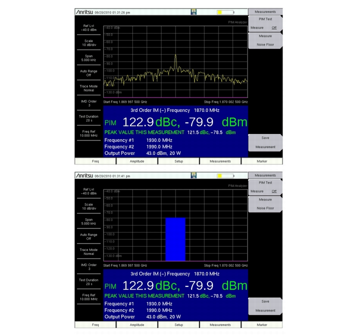
Press the Display Type submenu key to select the desired measurement view, Trace or Bar. Refer to Figure: “Spectral View vs. Graph View”.
|
 |
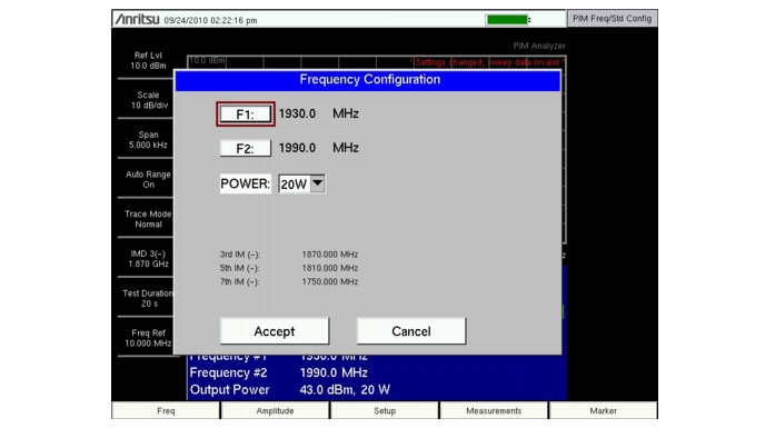
The Parameter Setup submenu under the Freq main menu or Setup main menu opens the Frequency Configuration dialog box (Figure: “Parameter Setup Display”). This dialog box displays the current carrier frequencies, power and intermodulations. In addition, frequencies for F1 and F2 as well as the carrier power can be changed in this dialog box.
 |