Reference Signal power displayed in dBm or Watts. The reference signal is used for downlink channel estimation.
The RMS (%) of all the error vectors, between the reconstructed ideal signals and the received signals, divided by the RMS value of the ideal signals.
The difference between the measured carrier frequency and the specified carrier frequency is the frequency error. This number is only as accurate as the frequency reference that is used, and is typically only useful with a good external frequency reference or GPS.
The peak (%) of all the error vectors, between the reconstructed ideal signals and the received signals, divided by the RMS value of the ideal signals.
Reference Signal power displayed in dBm. The reference signal is used for downlink channel estimation.
Primary Sync Signal power displayed in dBm or Watts. The primary sync signal is used to obtain slot synchronization. It contains information needed for cell search.
Secondary Sync Signal power displayed in dBm or Watts. The secondary sync signal is used to obtain frame synchronization and cell identity. It contains information needed for cell search.
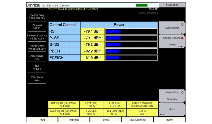
Physical Broadcast Channel Power. This physical channel carries system information for user equipment (UE) requiring access to the network.
Physical Control Format Indicator Channel Power. This channel provides information to enable the UE to decode the PDCCH and PDSCH channels.
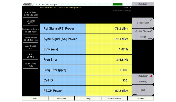
Modulation Summary displays the Ref Signal (RS) Power, Sync Signal (SS) Power, EVM (rms), Freq Error (Hz and ppm), Cell ID and PBCH Power in a table format. Refer to individual Modulation measurement descriptions for additional detail on each measurement.
|
1.
|
Press the Measurements main menu key.
|
|
2.
|
Press the Modulation submenu key.
|
|
3.
|
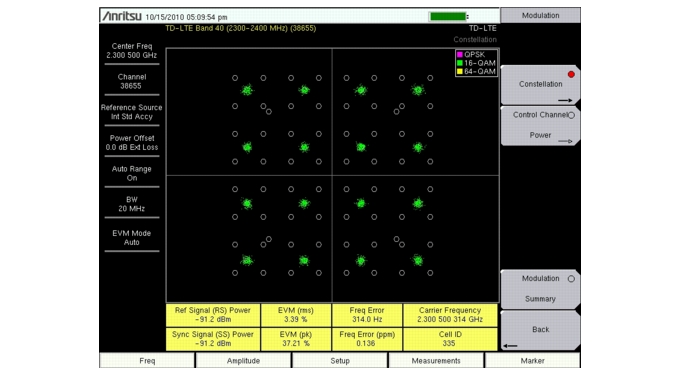
Press the Constellation submenu key to activate the Constellation measurement view (Figure: “Constellation Measurement View”). Press the Constellation submenu key again to list the Constellation menu to setup the reference points and data legend.
|
|
a.
|
Press the Reference Points submenu key to turn the reference points (small white circles) on or off.
|
|
b.
|
Press the Data Legend submenu key to turn the data legend on or off.
|
|
4.
|
Press the Back submenu key again to return to the Modulation menu.
|
|
1.
|
Press the Measurements main menu key.
|
|
2.
|
Press the Modulation submenu key.
|
|
3.
|
Press the Control Channel Power submenu key to activate the Control Channel Power display in table format (Figure: “Control Channel Power”).
|
|
4.
|
Press the Back submenu key to return to the Measurements menu.
|
|
1.
|
Press the Measurements main menu key.
|
|
2.
|
Press the Modulation submenu key.
|
|
3.
|
Press the Modulation Summary submenu key to activate and display the modulation measurements in table format (Figure: “Modulation Summary”).
|
|
4.
|
Press the Back submenu key to return to the Measurements menu.
|


