The test panel connector is shown in Figure: “Test Panel Connectors for MS272xC” and are described in the following text.
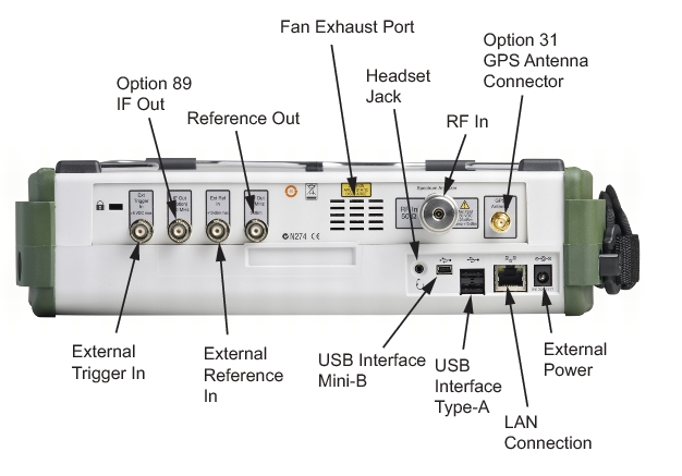 |
The external power connector is used to power the unit and for battery charging. Input is 12 VDC to 15 VDC at up to 5.0 A. A green flashing indicator light near the power switch shows that the instrument battery is being charged by the external charging unit. The indicator is steadily illuminated when the battery is fully charged.
|
When using the AC‑DC Adapter, always use a three‑wire power cable that is connected to a three‑wire power line outlet. If power is supplied without grounding the equipment in this manner, then the user is at risk of receiving a severe or fatal electric shock.
|
LAN Connection
The RJ‑45 connector is used to connect the Spectrum Master to a local area network. Integrated into this connector are two LEDs. The amber LED shows the presence of a 10 Mbit/s LAN connection when on, and a 100 Mbit/s LAN connection when off. The green LED flashes to show that LAN traffic is present. For additional information about the LAN connection, Ethernet connection, and DHCP, refer to “Ethernet Configuration”.
USB Interface – Type A
The MS272xC Spectrum Master can also be a USB Host and allow various USB Flash Memory devices to be connected to the instrument for storing measurements, setups, and files.
USB Interface – Type Mini‑B
The USB 2.0 interface can be used to connect the MS272xC Spectrum Master directly to a PC. The first time the MS272xC is connected to a PC, the normal USB device detection by the computer operating system will take place. The CD‑ROM that shipped with the instrument contains a driver for Windows XP that is installed when Master Software Tools is installed. Drivers are not available for earlier versions of the Windows operating system. During the driver installation process, place the CD‑ROM in the computer drive and specify that the installation wizard should search the CD‑ROM for the driver.
|
For proper detection, Master Software Tools should be installed on the PC prior to connecting the Spectrum Master to the USB port.
|
Headset Jack
The headset jack provides audio output from the built‑in AM/FM/SSB demodulator for testing and troubleshooting wireless communication systems. The jack accepts a 2.5 mm 3‑wire miniature phone plug such as those commonly used with cellular telephones.
Ref Out
The External Reference Out port is a BNC female connector that provides 10 MHz at 0 dBm.
Ext Ref In
The External Reference In port is a BNC female connector that provides for input of an external frequency reference.
IF Out 140 MHz (Option 89)
Ext Trigger In
A TTL signal that is applied to the External Trigger female BNC input connector causes a single sweep to occur. In the Spectrum Analyzer mode, it is used in zero span, and triggering occurs on the rising edge of the signal. After the sweep is complete, the resultant trace is displayed until the next trigger signal arrives.
RF In
50 Ω Type‑N connector (MS2722C, MS2723C, MS2724C) or a 50 Ω Type-K male ruggedized connector (MS2725C, MS2726C).
GPS Antenna Connector (Option 31)
The GPS antenna connection on the Spectrum Master is type SMA(F). Selectable +3 VDC or +5 VDC antenna power.