|
1.
|
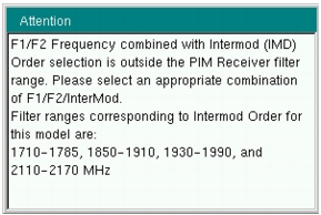
Press the Freq main menu key to display the frequency menu. Set Carrier F1 and Carrier F2 to generate the passive inter‑modulated signal. Carriers can be set anywhere in the range of 1930 MHz to 1990 MHz and 2110 MHz to 2155 MHz with a 0.1 MHz resolution. Attempting to set F1 or F2 outside of these ranges causes a message box to appear (refer to Figure: Carrier F1 or Carrier F2 Outside Frequency Range Error Message). Also, the software does not allow frequency pairs that create a PIM product (IMx) outside of the test system limits. The IMx is used to set the receiver center frequency. Figure: IMx Frequency Range Error Message is displayed when ranges outside of the limit are entered. Press ESC to clear the error message.
|
 |
|
3rd Order Intermodulation (IM3) = 2F1 – F2 or 2F2 – F1
5th Order Intermodulation (IM5) = 3F1 – 2F2 or 3F2 – 2F1 7th Order Intermodulation (IM7) = 4F1 – 3F2 or 4F2 – 3F1 Finding IM3 when F1 = 1930 MHz and F2 = 1990 MHz:
IM3 = 2F1 – F2 = 1870 MHz or 2F2 – F1 = 2050 MHz
The PIM Master will use 1870 MHz (low‑side IMx) as the center frequency. The PIM Master will always use the lower IMx value and will not set to the high‑side IMx frequency.
F1 = 1990 MHz and F2 = 1930 MHz, then the PIM Master will still use 1,870 MHz as the center frequency.
In addition, for the MW8219A, the IMx selection must be inside one of the two PIM Master receiver bands (listed below) to make a PIM measurement:
1710 MHz to 1785 MHz
1850 MHz to 1910 MHz If the IMx frequency does not fall within one of these bands, then the PIM Master displays an error message (Figure: IMx Frequency Range Error Message) and does not allow the measurement to occur.
|
 |
|
2.
|
Press the Carrier F1 submenu key to enter the frequency of Carrier F1 by using the keypad, the arrow keys, or the rotary knob. When entering a frequency by using the keypad, the submenu key labels change to GHz, MHz, kHz, and Hz. Press the appropriate unit key.
|
|
3.
|
|
4.
|
Press the Intermod Order submenu key so that the desired inter‑modulation frequency order to be viewed is underlined. 3rd order is the most commonly chosen measurement.
|
|
5.
|
Use the Span setting to set the frequency width in the display. Press the Span submenu key. The numeric value and units turn red ready for editing. Change the span to the desired width and press Enter. The preset span of 5 kHz is suitable for typical testing.
|
|
6.
|
Press the Amplitude main menu key to display the Amplitude menu.
|
|
7.
|
Press the Reference Level submenu key. The numeric value and units turn red indicating the settings are ready for editing. Enter the desired reference level using the keypad, the arrow keys, or the rotary knob. Press Enter.
|
|
8.
|
Press the Scale submenu key to change the division of the graticule to a setting other than the default value of 10 dBm.
|
|
9.
|
Press the Auto Range submenu key so that On is underlined. This allows the reference level to be adjusted automatically.
|
|
10.
|
Press the Amplitude Tone submenu key to have the handheld instrument broadcast a tone. The frequency of the tone increases as PIM level increases.
|
|
11.
|
Press the Setup main menu key to display the Setup menu.
|
|
12.
|
|
13.
|
Press the Test Duration submenu key. Enter the desired test time (time that the RF signal from the PIM Master is On) by using the keypad, the arrow keys, or the rotary knob. Then press Enter. The maximum time is 60 seconds.
|
|
14.
|
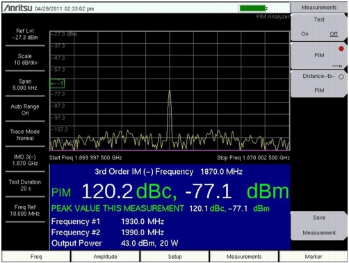
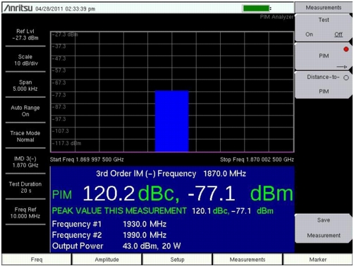
Press Normal‑>A to display the current sweep or Max Hold ‑> to display the cumulative maximum value of each display point from a series of sweeps.
|
|
15.
|
Press the Display Type submenu key to select the desired measurement view, Trace or Bar. Refer to Figure: Spectral Trace View and Figure: Bar Graph View.
|
 |
 |
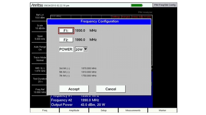
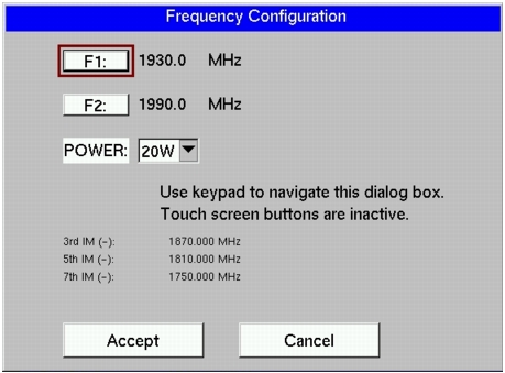
The Parameter Setup submenu (under the Freq main menu or Setup main menu) opens the Frequency Configuration dialog box (Figure: Parameter Setup Display). This dialog box displays the current carrier frequencies, power, and intermodulations. In addition, frequencies for F1 and F2 as well as the carrier power can be changed in this dialog box. Use the arrow keys or the rotary knob to scroll through the 3 settings (F1, F2, and Power). When one of these parameters is highlighted, press the Enter key. The chosen value changes color to indicate that the value is ready for editing. After editing the value, you must press the Enter key. The highlighted color changes to indicate that the new value has been set. For the power setting, pressing Enter for editing opens a drop‑down list. Highlight the desired power level and again press the Enter key. When all 3 settings are satisfactory, scroll to highlight the Accept button and press the Enter key. Instruments with a touch screen must use this same procedure, as indicated in the dialog box for those instruments (refer to Figure: Parameter Setup Display for Touch Screen Instruments).
 |
 |