1. On the VNA Master, press the Shift key, then the Mode (9) key.
2. Use the directional arrow keys or the rotary knob to highlight Power Monitor and then press the Enter key.
3. Connect the power sensor to the VNA Master RF Detector port.
Zeroing the Power Monitor
1. With no power applied to the Power Detector input, press the Zero soft key. Wait for a few seconds while the VNA Master accumulates data samples of the quiescent power.
2. When complete, Zero: On is displayed in the message area.
Measuring High Input Power Levels
1. Insert an attenuator between the DUT and the RF Detector to protect the VNA Master so that the power level is less than or equal to +16 dBm.
2. Press the Offset soft key and enter the attenuation by using the keypad, the arrow keys, or the rotary knob.
3. Press the Enter key to complete the entry.
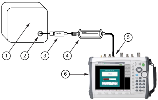
Power Measurement Setup With Attenuator
1
DUT (Device Under Test)
2
RF Out
3
Attenuator
4
RF Detector (Power Sensor)
5
RF Detector Interface (for Option 5)
6
VNA Master
Displaying Power in dBm or in Watts
Press the Units soft key to toggle between dBm and Watts.
Setting Relative Power
1. With the desired base power level input to the VNA Master, press the Relative soft key. The power reading shows 100 % because it is measuring the same power level.
2. If the power is lowered by 3 dB, then the relative power will show 50 %.
3. If the power in Watts is increased from 1 Watt to 2 Watts, then the relative power will show 200 %.
In Figure: Power Monitor Display, the Units are set for dBm, the Relative Power function is Off, the Offset is 1 dBm, and the Zero function is set to Off. The figure is intended to illustrate the general layout of the Power Monitor display. The displayed image on your instrument may be different.