The transmission feed line insertion loss test verifies the signal attenuation level of the cable. This test can be done using the Cable Loss or Return Loss Measurement with a short or an open connected at the end of the system. The advantage of using the Cable Loss measurement is that the instrument takes care of the math, and therefore no computations are needed. Cable Loss is a Return Loss measurement that also takes into consideration that the signal travels in both directions. Refer to Measure Menu – Single.
Procedure
1. If a test port extension cable is to be used, then connect it to the VNA Port 1 connector on the instrument.
2. Ensure that the instrument is in Vector Network Analyzer mode. Then press the Shift key and the System (8) key.
3. Press the Application Options soft key. The Meas Menu soft key toggles between Field and VNA. The active measurement function is underlined.
Press the soft key (if necessary) until Field is underlined, then press the Back key. The Measure menu now displays field measurement functions.
4. Press the Measure function hard key and then the Measurement Type soft key. From the Graph Type Selector list box, select Cable Loss and press Enter.
The Measurement Type soft key shows Cable Loss in the soft key face.
5. Press the Freq/Dist function hard key and set the Start Frequency and Stop Frequency.
6. Press the Sweep function hard key and then the Data Points soft key to set the number of data points (the larger the number of data points, the longer the maximum distance, at the expense of a slower sweep speed).
7. Press the Shift key, then the Calibrate (2) key.
8. Press the Start Cal soft key and perform a 1‑port OSL calibration at the connector or at end of the extension cable. Follow the instructions on the display.
9. When the Calibration is finished, CAL: ON (OK) should be displayed with the trace data in the instrument settings summary at the left side of the sweep window, and the trace should be centered around 0 dB when the short or open is connected.
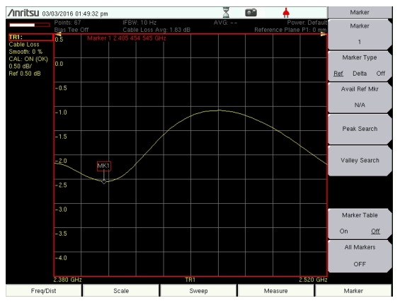
10. Connect the test port extension cable to the Transmission Line to begin the Cable Loss measurement. The example below shows a cable loss measurement in the WiFi band. Average cable loss is calculated and displayed at the top of the graticule.
Display Type Single – Cable Loss
11. Use the File menu to save the measurement. Refer to the file management instructions in the user guide for your instrument.