Use the following procedures to quickly prepare for all measurements by utilizing the built‑in features of the instrument and the software.
|
1.
|
Attach the antenna to the Spectrum Analyzer RF In connector (refer to the User Guide for your instrument for connector identification and location).
|
|
a.
|
|
b.
|
|
c.
|
|
d.
|
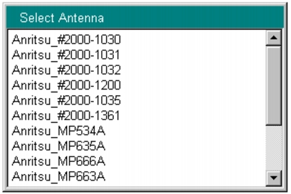
Press the Antenna (Correction Level) submenu key to open the Select Antenna list box (refer to Figure: Select Antenna List Box).
|
|
e.
|
Scroll through to the desired Anritsu antenna model number by using the Up/Down arrow keys or the rotary knob. Highlight the antenna model number, and then press Enter.
|
 |
You can use Master Software Tools (MST) to update your antenna and coaxial cable lists. For directions about updating these lists, refer to the Master Software Tools documentation on the MST CD‑ROM that was supplied with your Anritsu instrument.
|
1.
|
Press the Frequency/Level main menu key.
|
|
2.
|
Configure the following parameters: Channel Map, Frequency, Bandwidth, Auto Reference Level, Reference Level, and Pre Amp.
|
|
a.
|
|
b.
|
Select one of the available choices, then press the Enter button.
|
If you selected UHF or UHF (Brazil), then press the Channel submenu key, scroll through to the desired channel, highlight it, and press Enter. Continue at Step 4.
|
c.
|
Press the Frequency submenu key to open the Frequency Editor dialog box. The menu changes to Units (Hz, kHz, MHz, GHz). The available frequency range step increments are displayed in the dialog box.
|
|
d.
|
Scroll through to a desired frequency by using the Up/Down arrow keys or the rotary knob, and then press Enter. You can also type the frequency by using the number keypad and then pressing one of the submenu keys in the Units menu. Pressing the Enter key is the same as pressing the MHz submenu key. The frequency can be set from 35 MHz to 806 MHz.
|
|
3.
|
Press the Bandwidth submenu key and select the desired bandwidth frequency, 6 MHz or 8 MHz. Note that the 8 MHz bandwidth should be selected only when Channel Map is set to None. It can be selected for the Field Strength, Modulation Analysis, and Spectrum Monitor measurements in the Custom setup procedure.
|
|
4.
|
|
5.
|
Scroll through to the desired dBm level by using the Up/Down arrow keys or the rotary knob, and then press Enter. Only the 10 dB increments are available, you cannot use the numeric keypad.
|
6.
|
|
7.
|
Press the One‑Seg submenu key to toggle the selection to the desired state, On or Off. When this submenu key is toggled to On, the frequency response measurement is displayed for the center segment (the center channel of the 13 chosen channels). Refer to Figure: Modulation Analysis of Delay Profile, One‑Segment. Note that the One‑Seg feature may be selected only when the Bandwidth is set to 6 MHz. It is used for Field Strength, Modulation Analysis, or Spectrum Monitor measurements.
|