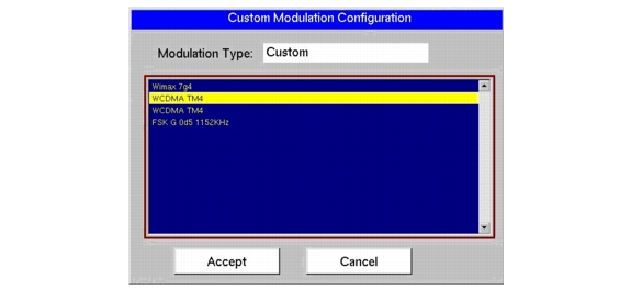
Modulation patterns are available for both the signal patterns and the interferer patterns. These patterns are presented in a dialog box, which is shown in Figure: Custom Modulation Configuration.
To open the Custom Modulation Configuration dialog box. press the Modulation main menu key, then press either the Signal Pattern submenu key or the Interferer Pattern submenu key, then press the Custom submenu key. Refer to Figure: Modulation Menu, Figure: Edit Signal Menu, and Figure: Edit Interferer Menu.
To select a custom pattern to use as signal or interferer, press the Custom submenu key to open the dialog box Custom Modulation Configuration, which also opens the Modulation Config menu (shown in Figure: Main Menu Keys). A Custom submenu key is available in two menus: Figure: Edit Signal Menu and Figure: Edit Interferer Menu.
Set up the signal and interferer patterns to one of three types of modulation: analog, digital, or custom.
In the following 3 procedures, the signal pattern or interferer pattern is chosen.
In the following procedure, you are directed to choose a Modulation Type, a Rate, and a Deviation for a signal pattern, or you are directed to choose a Modulation Type, a Frequency, and a Depth for an interferer pattern. When selected, these parameters are displayed in the lower section of the sweep window. Refer to “Signal Data” and “Interferer Data” in Figure: VSG Levels Display (example only, your instrument may differ).
|
1.
|
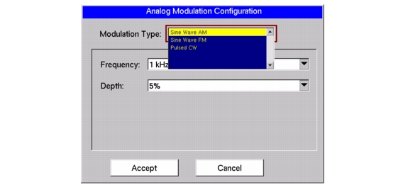
From the Modulation menu, and after pressing either the Signal Pattern or the Interferer Pattern submenu key, press the Analog submenu key. The Analog Modulation Configuration dialog box opens with the Modulation Type list box highlighted in red. The following figure is an example only. Your instrument may show a different list.
|
 |
|
2.
|
|
3.
|
Highlight the desired modulation type by using the Up/Down arrow keys or the rotary knob, and then press Enter.
|
|
a.
|
(Signal or Interferer) If the Modulation Type is “Sine Wave AM”, then the subsequent choices are “Frequency” and “Depth”.
|
|
b.
|
(Signal or Interferer) If the Modulation Type is “Sine Wave FM”, then the subsequent choices are “Rate” and “Deviation”.
|
|
c.
|
(Signal only) If the Modulation Type is “Pulsed CW”, then the subsequent choices are “Duty Cycle” and “Period”.
|
|
4.
|
Use the Up/Down arrow keys or rotary knob to highlight the desired Frequency, Rate, or Duty Cycle list box and then press the Select submenu key, or press Enter.
|
|
5.
|
Highlight the desired value (using either the Up/Down arrow keys or the rotary knob) and press Enter.
|
|
6.
|
Use the Up/Down arrow keys or rotary knob to highlight the Depth, Deviation, or Period list box and then press Enter.
|
|
7.
|
Highlight the desired value (using either the Up/Down arrow keys or the rotary knob) and press Enter.
|
|
8.
|
Use the Up/Down arrow keys or rotary knob to highlight the Accept button (or the Cancel button) and then press Enter, or press the Accept submenu key (or Cancel submenu key).
|
In the following procedure, you are directed to choose a Modulation Type and a signal pattern or an interferer pattern. When selected, each pattern identification is displayed in the lower section of the sweep window. Refer to “Signal Data” and “Interferer Data” in Figure: VSG Levels Display (example only, your instrument may differ).
|
1.
|
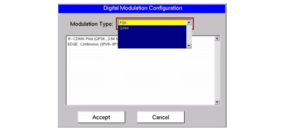
Press the Digital submenu key. The Digital Modulation Configuration dialog box opens with the Modulation Type list box highlighted in red. The following figure is an example only. Your instrument may show a different list.
|
 |
|
2.
|
Press the Enter button or press the Select submenu key to select one of the modulation waveform types.
|
|
3.
|
Highlight the desired modulation type by using the Up/Down arrow keys or the rotary knob, and then press Enter or press the Select submenu key. The pattern list box is updated to show the available patterns for the chosen modulation type, and one pattern is highlighted.
|
|
4.
|
Use the Up/Down arrow keys or rotary knob to highlight the pattern list box and press the Select submenu key.
|
|
5.
|
|
6.
|
After selecting the pattern type, use either the Up/Down arrow keys or the rotary knob to highlight the Accept button (or the Cancel button) and then press Enter, or press the Accept submenu key (or the Cancel submenu key).
|
In the following procedure, you are directed to select a custom modulation pattern. When selected, the pattern identification is displayed in the lower section of the sweep window. Refer to “Signal Data” and “Interferer Data” in Figure: VSG Levels Display (example only, your instrument may differ).
|
Custom patterns must be loaded into VSG Custom Signal Pattern memory before they are listed in the Custom Modulation Configuration window. See VSG Custom Pattern Management for instructions pertaining to loading a pattern.
|
|
1.
|
Press the Custom submenu key. The Custom Modulation Configuration dialog box opens. The following figure is an example only. Your instrument may show a different list.
|
 |
|
2.
|
The list is already active. Use the Up/Down arrow keys or the rotary knob to highlight a custom signal pattern and then press the Select submenu key or press Enter.
|
|
3.
|
Select the Accept button or the Cancel button and then press Enter to either accept or abort and return to the previous menu (or press the Accept submenu key or the Cancel submenu key).
|
For some cases of BER testing, the signal spectrum needs to be inverted. Spectrum inversion may also be needed if a mixer is used to convert the VSG output frequency.