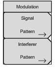
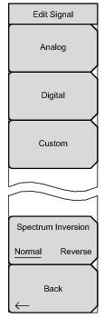
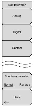
Key Sequence: Modulation
 |
 |
 |
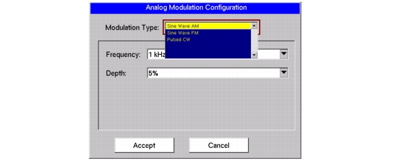 |
When generating an AM sine wave, 7 discrete frequency settings are available, as shown in Table: Sine Wave AM – Frequencies. After selecting a frequency, choose one of 7 settings for Percent Depth as shown in Table: Sine Wave AM – Percent Depth.
|
400 Hz
|
|
1 kHz
|
|
3 kHz
|
|
5 kHz
|
|
10 kHz
|
|
15 kHz
|
|
20 kHz
|
|
5 %
|
|
10 %
|
|
20 %
|
|
30 %
|
|
50 %
|
|
70 %
|
|
90 %
|
When generating an FM sine wave, 6 discrete rate settings are available, as shown in Table: Sine Wave FM – Rates. After selecting a rate, choose one of 8 settings for Deviation in hertz, as shown in Table: Sine Wave FM – Deviations.
|
1 kHz
|
|
5 kHz
|
|
10 kHz
|
|
50 kHz
|
|
100 kHz
|
|
500 kHz
|
|
100 Hz
|
|
500 Hz
|
|
1 kHz
|
|
5 kHz
|
|
10 kHz
|
|
50 kHz
|
|
100 kHz
|
|
500 kHz
|
Pulsed CW
Pulsed CW is available only as a single channel. Choose one of 3 settings for the period, as shown in Table: Period Settings for Pulsed CW.
|
0.1 msec (10 kHz)
|
|
1 msec (1 kHz)
|
|
2.5 msec (400 Hz)
|
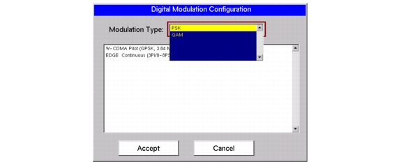 |
The digital modulation types and their associated signal patterns are shown in Table: Digital Modulation Configuration.
|
W-CDMA Pilot (QPSK, 3.84 Msym/s, RRC, alpha=0.22, PN9)
EDGE Continuous (3Pi/8-8PSK, 270.833 ksym/sec, Lin-Gauss, PN9)
|
|
|
DECT 16 QAM Continuous (1.152 Msym/s, RRC, alpha=0.5, PN9)
J.83C Digital Cable (16 QAM, 5 Msym/s, RRC, alpha=0.13, PN9)
DVB-C (16 QAM, 6.84 Msym/s, RRC, alpha=0.15, PN9)
DECT 64 QAM (1.152 Msym/s, RRC, alph=0.5, PN9)
US Digital 64 QAM (5.056941 Msym/s, RRC, alpha=0.18, PN9)
|