When this submenu key is pressed the instrument toggles between single sweep and continuous sweep. In single sweep mode, after the sweep the instrument waits in Hold mode until the Manual Trigger submenu key is pressed or another triggering mode is selected.
Several sweep modes are available on the instrument. Press the Sweep Mode submenu keys to select between Fast (default), Performance or No FFT. The Show Help submenu key displays a table detailing the trade-off between sweep speed and performance of the sweep mode options.
|
Fast is the default sweep mode for instruments that have received the
New Instrument calibration from Anritsu. |
Several detection methods tailor the performance of the instrument to meet specific measurement requirements. In general, there are more measurement points across the screen than display points. The various detection methods are different ways of dealing with how measurement point data is shown at each display point.
Peak: This method causes the largest measurement point to be shown for each display point, and assures that a narrow peak is not missed.
RMS: This method performs a root-mean-square calculation of all the measurement points in each display point, and is particularly useful in displaying the average value of noise.
Negative: This method causes the smallest measurement point to be shown for each display point. Typically this mode is used to help detect small discrete signals in the presence of nearly equal values of noise. The display points that contain only noise will tend to show lower amplitudes than those that contain discrete signals.
Sample: This is the fastest detection method because for each display point, only one frequency point is measured. Use this method when speed is of paramount importance and the possibility of missing a narrow peak is not important.
Quasi-peak: When this selection is made resolution bandwidths and video bandwidths of 200 Hz, 9 kHz and 120 kHz are available. This detection method is designed to meet CISPR requirements.
To select a specific type of triggering, press the Trigger Type submenu key. Selections are:
Free Run: The default trigger type is “Free Run” in which the instrument begins another sweep as soon as one is finished.
External: A TTL signal applied to the External Trigger BNC input connector causes a single sweep to occur. This mode is used in zero span, and triggering occurs on the rising edge of the signal. After the sweep is complete, the resultant trace is displayed until the next trigger signal arrives.
Video: This mode is used in zero span to set the power level at which a sweep is initiated. The power level can be set from –130 dBm to +30 dBm. Trigger is based on the measured signal level. The sweep triggers when the signal level crosses the trigger level with a positive slope. If no signal crosses the trigger level, the last trace on the screen, before video triggering was selected, will be displayed. To change the video triggering level use the rotary knob, enter the desired amplitude with the keypad, or use the Left/Right arrows to change the setting by 1 dB or the Up/Down arrows to change the setting by 10 dB.
Change Trigger Position: This submenu key is used in conjunction with video triggering to set the horizontal position on the display where a signal that meets the video triggering criterion will be placed. The value can be from 0% to 100%. Zero percent places the triggering event at the left edge of the screen while 100% places the triggering at the right edge of the screen. When the trigger position is any value other than 0%, the portion of the trace before the trigger event is displayed very quickly because the trace data is stored in memory. The portion of the trace after the trigger point is painted on the screen at the normal rate as the signal is swept.
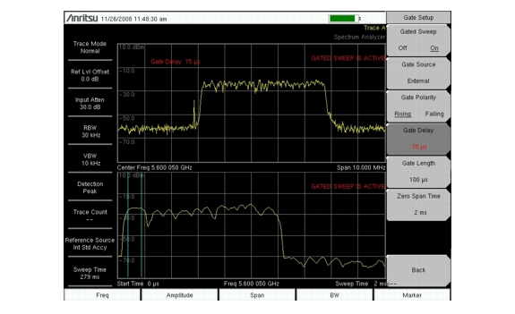
Gated Sweep Setup (Option 90 Only): The Gated Sweep function allows you to view a signal in time and frequency domain. Pressing the Gated Sweep Setup splits the screen into two graphic displays, frequency domain (top) and time domain (bottom). In addition, the Gate Setup menu is listed for setting up the parameters for Gated Sweep: gate polarity, gate delay, gate length, and zero span time. In reference to the time domain display, zero time span is the time set for the full horizontal length of the screen, the gate delay sets the left vertical blue line or start of the gate sweep, and the gate length sets the right vertical blue line or end of the gate sweep. The gated sweep signal is displayed in frequency domain on the top graphic display.
|
Screen captured images are provided as examples. The image and measurement details shown on your instrument may differ from the examples in this user guide.
|
 |