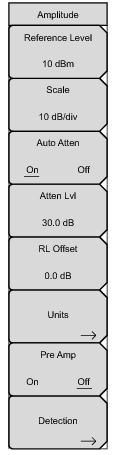
The reference level is the top graticule line on the display, and can be set from +30 dBm to –130 dBm. A value may be entered from the keypad, use the ± key for a minus sign. After entering the value press the dBm submenu key or the
Enter key. The
Up/Down arrow keys change the reference level in 10 dB steps, and the
Left/Right arrow keys change the value by 1 dB. The rotary knob changes the value by 0.1 dB per click. The reference level value may be modified by the reference level offset value to compensate for an external attenuator.
The scale can be set in 1 dB steps from 1 dB per division to 15 dB per division. The value can be changed using the keypad, the rotary knob or the arrow keys.
Input attenuation can be either tied to the reference level (On) or manually selected (Off). When input attenuation is tied to the reference level, attenuation is increased as higher reference levels are selected to make sure the instrument input circuits are not saturated by large signals that are likely to be present when high reference levels are required.
Reference Level Offset compensates for the presence of an external input attenuation or gain. Enter a positive value to compensate for an external amplifier, or a negative value to compensate for an external attenuator. Use the ± key to enter the negative sign when a negative attenuation value is being entered.
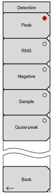
Press the Back submenu key to return to the Amplitude menu.
This submenu key turns the low-noise front-end preamplifier on or off. To assure accurate measurement results, the largest signal into the instrument input when the preamplifier is turned on should be less than –40 dBm.
Several detection methods tailor the performance of the instrument to meet specific measurement requirements. In general, there are more measurement points across the screen than display points. The various detection methods are different ways of dealing with selecting which measurement point will be shown at each display point. Opens the
“Detection Menu” on page 2‑31.