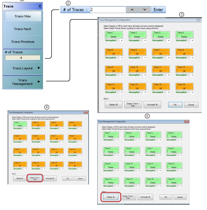
3. Trace Management Configuration – Traces 1 through 4 set to Display
4. Trace Management Configuration – Display All selected. All traces set to display
5. Trace Management Configuration – Trace 1 Selected to display.
Note: At least one trace must be selected to be in “Display” mode. If the “Configure” button is clicked in the Trace Management Configuration dialog after setting all trace displays to “Off”, the dialog will closed without error but Trace 1 display setting will be internally set to “Display” mode and hence only Trace 1 will be displayed by default for the selected channel.
Trace Max
Select displays the currently active trace and maximizes the display to fill the screen. Select again to return to the normal trace display.
Trace Next
Select activates the next higher trace number. If the highest trace was previously selected, trace 1 (one) is activated.
Trace Previous
Select activates the next lower trace number. If trace 1 (one) is was previously selected, the highest numbered trace is selected.
# of Traces
Selecting the # of Traces (Number of Traces) button allows the user to define the number of traces that appear on the screen and displays the # of Traces field toolbar. On the toolbar, from 1 (one) to 16 traces per channel can be selected.
• If the number of traces is greater than the current trace display layout (described below), traces will be overlaid as required. For example, if the # of Traces selection is set to 6 (six) traces, and the trace layout is set to 4 (four) traces, 2 (two) of the trace displays will be overlaid with an additional trace.
• If the number of traces is less than the current trace display layout, trace display positions will be empty. For example, if the trace layout is for 16 traces (4 rows of 4 displays), and the # of Traces selection is set for 12 traces, the last row of three trace displays will be empty.
Trace Layout
Select displays the TRACE LAYOUT menu to change how the traces are displayed on the screen.
Select displays the TRACE MANAGEMENT CONFIGURATION dialog to select which traces are displayed on the UI.
Traces can be left uncoupled or can be assigned to one of two coupled groups (A and B). Within a coupled group, the graph types and scales are forced to be the same. If a new member is added to a group, it is coerced to the format of the others in the group, and changing format of any member of the group will change the format of all members of the group.
The grouping process facilitates dual-Y-axis displays when multiple traces are overlaid. If members of A and B groups are overlaid and a member of either group is the active trace, both Y-axes will be displayed (with A and B annotations). If an uncoupled trace is active in such an overlay situation, only the Y-axis for that trace will be visible.