LRL (Line-Reflect-Line) uses two (or more) transmission lines and a reflect standard (for each port). The line lengths are important as it is required that the two lines look electrically distinct at all times (meaning it will not work at DC nor at a frequency where the difference in length is an integral number of half wavelengths). The reflect standard is assumed to be symmetric and without a high return loss. The lines are assumed perfect (no mismatch), and are usually airlines for coaxial calibrations, although other structures can be used. On-wafer transmission lines can be very good and this calibration approach will work well if the required probe movement can be managed.
LMR - Line-Reflect-Match
LRM (Line-Reflect-Match) and ALRM (Advanced Line-Reflect-Match) calibrations have one of the lines above replaced with a match (or load). The load is modeled/characterized (or assumed perfect). Since only one line is involved, this calibration can work down to DC and up to very high frequencies (practically limited by the match knowledge/characterization). Variations allow one of the match measurements to be traded for a pair of additional reflect measurements (a second reflect standard is needed). Because of the requirement that the reflect standards be distinct, the calibration may become band limited.
In the limiting case of a match that is assumed perfect, or at least assumed symmetric, this calibration reduces to the classical LRM. The added flexibility is in the ability to define asymmetric load models and to use multiple reflect standards as discussed above. The double reflect methodology allows one to feed into a load modeling utility where the load model can be further optimized.
Some parameters to keep in mind:
Line Lengths
In addition to the LRL frequency limits, the line length is used for some reference plane tasks. The fundamental reference plane of an LRL/ALRM calibration is in the middle of the first line. If the reference plane is required at the ends of this line, the line length (and loss which can also be entered) is used to rotate the reference planes to the desired location. The line length delta is also used for some root choice tasks, although the accuracy required on this entry is less.
Line Length Delta
As mentioned above, the usable frequency range for LRL is set by the line length delta. Strictly speaking, the electrical length should be between 0 and 180 degrees for all frequencies of interest although some margin is usually desired to account for line parasitics, spurious mode launches and other problems. In general, the delta should be kept between 10 and 170 degrees or 20 and 160 degrees. Practically speaking, one can usually be more aggressive on the lower number and will want to be less aggressive on the upper number:
(Eq. 6-1)
Where ΔL is in meters, vph is the phase velocity of the line (= 2.9978 108m/s = c for air dielectric) and f can be any frequency in the range of interest, expressed in Hz.
If this range is too small for the application, multiple lines and multiple bands can be used. Each band uses a line pair covering some range of interest. LRL can be combined with LRM/ALRM (LRM/ALRM usually covering the low frequency end) within the calibration system. When two bands are used, a frequency break point must be specified to indicate when to switch from one calibration to the other. A suggestion can be calculated and this will be done based on the line lengths entered.
The setup dialog for LRL/LRM/ALRM is quite flexible with decisions made based on what standards are selected. Several examples are shown in the figures below.
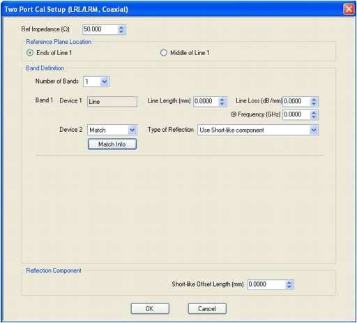
TWO PORT CAL SETUP (LRL/LRM, COAXIAL) Dialog Box
Typical parameters - One-Band LRL calibration
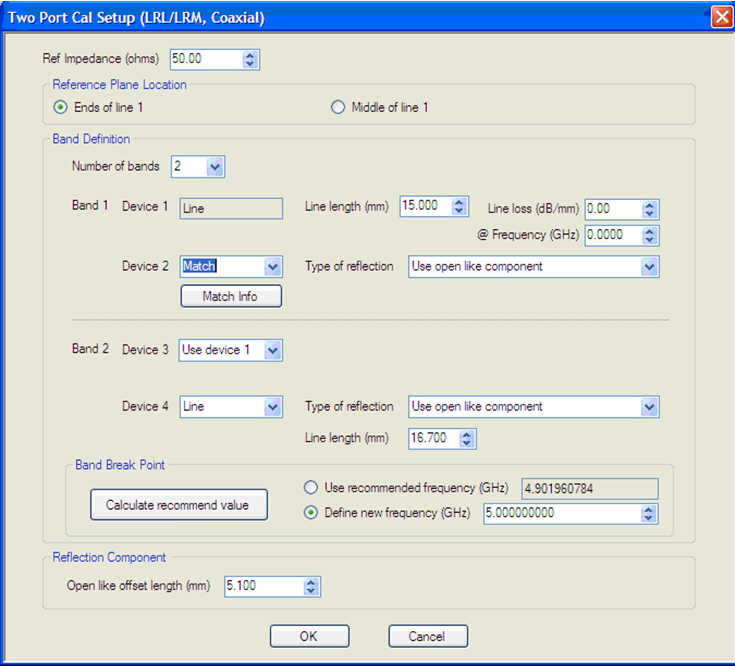
TWO PORT CAL SETUP (LRL/LRM, COAXIAL) Dialog Box
Typical parameters - Band 1 LRM/ALRM - Band 2 LRL
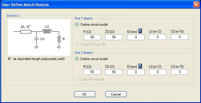
USER DEFINED MATCH DEVICES Dialog Box
Typical parameters - Defining the Load for ALRM (match info)
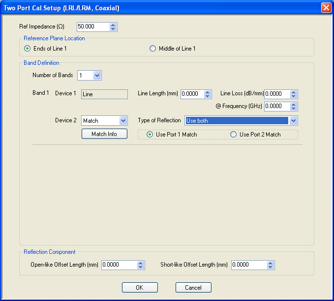
TWO PORT CAL SETUP (LRL/LRM, COAXIAL) Dialog Box
Typical parameters - One Band ALRM Using Two Reflects
The Cal Merge (concatenation) utility can also be used with any other calibration types in order to cover a wider frequency range.
Reflection Offset Length and Reflection Type
Some information is requested about the reflection although a full characterization is not needed. The information is used in some root-choice activities and it only needs to be known if the reflect behaves more like an open or a short (since typically opens and shorts are used as the reflect standard). The offset length is used to dynamically move the reference planes around so the algorithm will know what the reflect looks like at any given frequency.
In the double reflect ALRM methodology it is important that the reflect standards be distinct. More specifically, they must be distinct when rotated to the reference plane at the center of line 1. Since large offset lengths will lead to many more degeneracies, this double reflect option will generally be used when offset lengths are smaller (such as in on-wafer of fixtured calibrations).
Load Model/Characterization for ALRM
When a single reflect approach is taken within ALRM, it behaves like a classical LRM. For slightly more advanced use, complete load models can be entered for the two matches independently. The same model as described for SOLT applies.
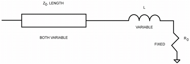
At the highest level, two reflects are measured per port to allow more optimized information to be obtained. When the double reflect methodology is selected, an optimization routine can be selected which can lead to a load model. The structure below is used (similar to that for the general model except no capacitance). The resistance element is assumed known (whether from DC measurements or other parametric data). The inductance and transmission line parameters can be optimized over given ranges.
Load Model/Characterization for ALRM
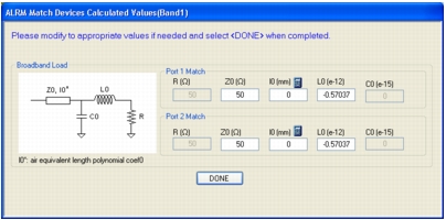
The dialog box (Figure: ALRM MATCH DEVICES CALCULATED VALUES (BAND 1) Dialog Box below) pertaining to this model will appear after the main calibration steps are complete. At that point, the fit model can be used (default) or modified values can be entered. A model will be suggested by the algorithm but can be overridden in this dialog.
ALRM MATCH DEVICES CALCULATED VALUES (BAND 1) Dialog Box
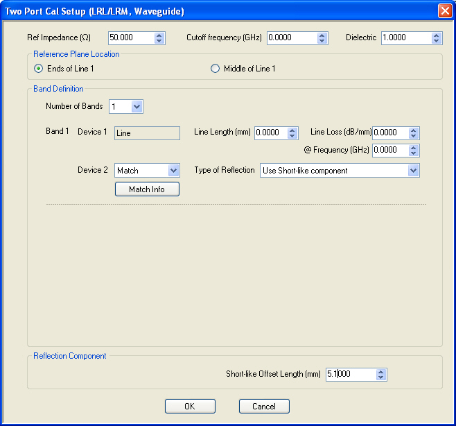
An example LRL/ALRM setup dialog for a waveguide line type is shown here. Note the cutoff and dielectric constant line items that are added.
An Example LRL/ALRM Setup Dialog for a Waveguide Line Type
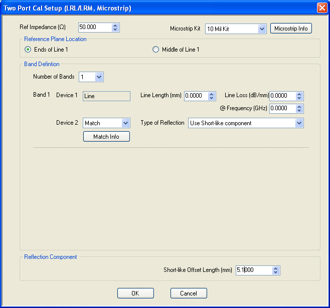
An example LRL/ALRM setup dialog for a microstrip line type is shown here. Note the media line items that have been added (the microstrip info sub-dialog is described earlier).
An Example LRL/ALRM Setup Dialog for a Microstrip Line Type
When using the double-reflect ALRM method, it is important to note that the reflections must produce distinct reflection coefficients when rotated to the central reference plane. When the reflect offset lengths start to become large, this gets to be more difficult over large frequency ranges. In an on-wafer environment when the offset lengths are typically very short, this does not present a problem but it can be an issue in coax. Since the load modeling is most commonly an issue in high frequency on-wafer measurements, this behavior is usually consistent with the applications.