The concept of the adapter removal relies on the existence of two related sets of reference planes with one set on either side of the adapter (see Figure: Adapter Removal Block Diagram below). Assuming one can perform a full calibration at each set of reference planes, there is enough information to extract the behavior of the adapter itself. When the calibration is being performed at the reference planes on the left (between Ports 1 and 2’), the adapter behavior is embedded in the characteristics of Port 2’.
Similarly, when the calibration is being performed between Ports 1’ and 2, the adapter behavior is embedded in that of Port 1’. Since each of these two calibrations involve mating connector types, these are far easier to perform than the direct 1-2 calibration. It will not be shown here, but the use of the two calibrations provide nearly enough information to extract the parameters of the adapter itself. Figure: Adapter Removal Block Diagram shows the structure of the adapter removal calibration. Two calibrations are performed at the two sets of reference planes shown (between Ports 1 and 2’, and between 1’ and 2), which allows a determination of the adapter behavior. After the adapter removal, the resulting calibration will be between Ports 1 and 2.
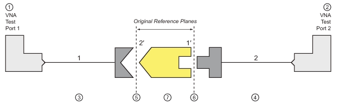
Adapter Removal Block Diagram
1. Test Port 1
2. Test Port 2
3. Port 1 Test Cable
4. Port 2 Test Cable
5. Original Reference Plane 2’, when adapter is connected to Port 2 Test Cable
6. Original Reference Plane 1’, when adapter is connected to Port 1 Test Cable
7. Adapter to be calibrated
Caveats and Limitations
There are two caveats to this procedure.
First, only the S12S21 products of the adapter can be determined from this procedure, not the two transmission terms individually. However, since only the product is needed to de-embed the adapter effects, this is not much of a problem. Most adapters are passive and reciprocal anyway, so the individual terms could be determined if necessary.
Second, there is a complex square root operation involved, so a root determination is necessary. To help this, the user must enter a guess as to the electrical length of the adapter (in ps of delay). The guess need not be very accurate, just within the correct half plane. At 2 GHz, this means the error in delay entry should be less than 125 ps to ensure the correct root is selected.
In general the error must be less than where f is the highest frequency being used.