Both lowpass and bandpass work similarly with regards to gating. Gating is the process of selecting or deleting certain defects to study. This can be left in time domain but, more commonly, the gated results are fed back through the forward transform to get the frequency domain result corresponding to the modified defect scenario just created.
Gate Menu
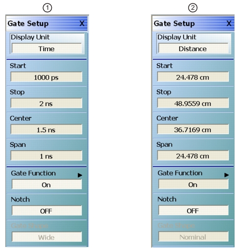
The Gate menu looks much like the Range Menu. The Display Unit toggle button and Start, Stop, Center, and Span buttons (for the gate this time) control values as described in the sections above.
GATE SETUP Menu
1. Time units (at left)
2. Distance units (at right)
The Notch toggle selects the polarity of the gate. When notch is OFF, the gate will keep everything between start and stop. When notch is ON, the gate will reject everything between start and stop. The main submenu, Gate Function, is shown in Figure: Gate Function Submenu.
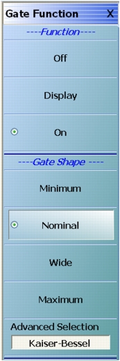
Gate Function Submenu
The default gate shape is nominal. By default, the gate is off. Selecting Display will allow the gate function to be drawn on screen (using the current graph type for the active trace). This can be helpful in visualizing what is being included in the gate. Turning gate on will apply the gate to the current time domain data.
The gate shape is analogous to the window selection. If the data was truncated with a sharp gate (minimum, akin to rectangular), maximum resolution in used determining the gate but ripple is introduced in the frequency domain. For more gradual gates, the resolution in separating defects decreases, but the size of the artifacts added to the frequency domain data decreases as well.
The window and gate shapes cannot be selected entirely independently since they interact through the transform. In particular, the use of a very sharp gate with a low side lobe window can lead to large errors. The allowed combinations are shown in the table below. If an invalid combination is selected, the variable not being currently modified will be changed to the nearest valid value.
Window Type and Gate Shape Allowed Combinations
Window/Gate
Minimum
Nominal
Wide
Maximum
Rectangular
OK
OK
OK
OK
Nominal
OK
OK
OK
OK
Low side lobe
No
OK
OK
OK
Minimum side lobe
No
No
OK
OK
With the advanced gates and windows, selections are not precluded although substantial errors can result if values are chosen without caution. If a more aggressive window is chosen (larger beta or side lobe level), then the gate must be wider (wide or maximum; larger beta or side lobe level).
DUT Example - Gate and Window Nominal
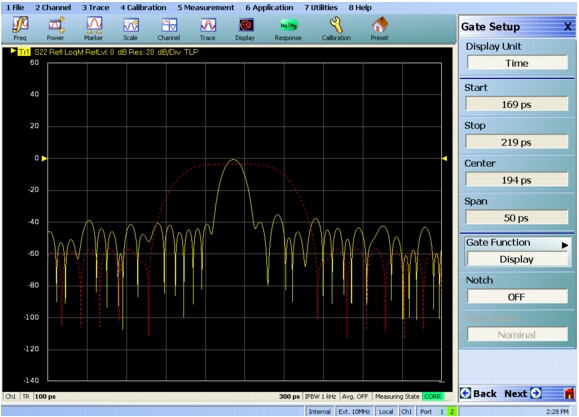
To work through an example, a DUT consisting of a short at the end of a slightly mismatched transmission line is used. It is desired to examine the short more closely in frequency domain, excluding the effects of the transmission line. In Figure: Gate in Display Mode Example, the gate is in display mode surrounding the desired reflection. Both gate and window are set to nominal in this case.
Gate in Display Mode Example
Gate is the red dashed line
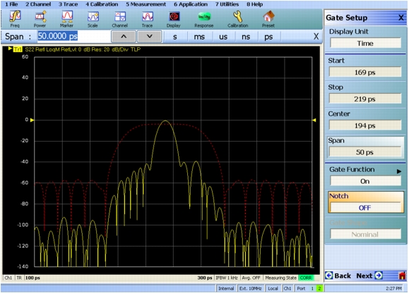
Next the gate is turned to on. In Figure: Gate Turned On Example, the suppression of the time domain information outside of the gate area is seen.
Gate Turned On Example
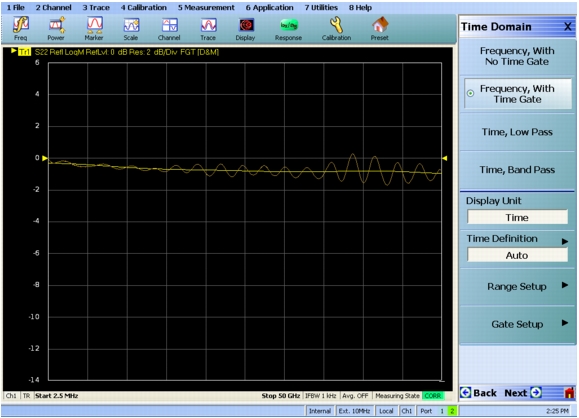
Finally, frequency with time gating is activated and the result is shown in Figure: Frequency with Time Gating Example. The result from frequency without time gating is shown in memory as a darker trace. The time gating has removed much of the ripple due to the mismatched transmission line and residual source match of the instrument.