The key concepts to setting up multiple source control are:
Four External Sources for MS4640A VNAs
For MS464A Series VNAs, up to four (4) external sources can be configured.
Frequency Plan Bands
The frequency plan is separated into “bands”. There may be as many as 50 or as few as one. One needs multiple bands ONLY if the relationship between sources and the receiver change in an unusual way at some point in the sweep. Examples:
• A mixer measurement is being setup where the RF and LO are offset by a fixed amount and the IF (which will be sent to the VNA receiver) is constant. Only one band is needed.
• A harmonic converter is being tested where it operates on the 2nd harmonic of the LO up to 10 GHz and the 3rd harmonic beyond that. Two bands are needed here.
Linearly Linked Source Frequencies
All source frequencies (internal or external) and the receiver frequency must be linearly related. All are expressed as linear equations as a function of a runner variable “f”. This variable f is always the one displayed on the X-Axis although it need not represent an actual frequency (although for convenience it usually does).
These linear relationships can change in different “bands” that the user defines. The band edges are always in terms of the runner variable f.
Band Start Frequency, Band Stop Frequency, and Runner Variable f
The band start and stop frequencies are in terms of the runner variable f. Thus they may or may not be physical. To reiterate, the choice is usually based on what one wants the X-Axis of the plots to be labeled in terms of (e.g., in terms of the RF frequency or in terms of the IF frequency for a mixer measurement).
MULTIPLE SOURCE Menu
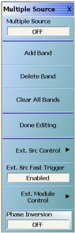
The main multiple source setup menu is shown below in Figure: Main MULTIPLE SOURCE Setup Menu. The top half of the menu, pertaining to equation editing, will be dealt with first. The special functions of the lower half of the menu will be discussed later.
Main MULTIPLE SOURCE Setup Menu
The MULTIPLE SOURCE menu appearance differs slightly depending on the instrument model number, installed options, and band edit state.
• Multiple Source and Phase Inversion are set to OFF.
• Changing Multiple Source here also changes the selection on the APPLICATION menu.
• External Source Fast Trigger set to Enabled.
• Phase Inversion set to OFF.
The top button on the menu toggles Multiple Source mode on or off, similar to the mode selection buttons on the APPLICATION menu (turning Multiple Source mode off here will change the mode on the APPLICATION menu to Standard). When this menu is entered, the MULTIPLE SOURCE tableau will appear in the lower part of the screen (Figure: MULTIPLE SOURCE Tableau below).
Note
The Done Editing button in the Multiple Source menu MUST be clicked for new values to take effect.
Band frequency ranges DO NOT define a required start and stop frequency. These merely set the min and max possible for start and stop. Readjust the desired range for actual measurements on the frequency menu.
When the MULTIPLE SOURCE tableau first appears, the first band is in the table. The Add Band, Delete Band, and Clear Band buttons will have the obvious effects.
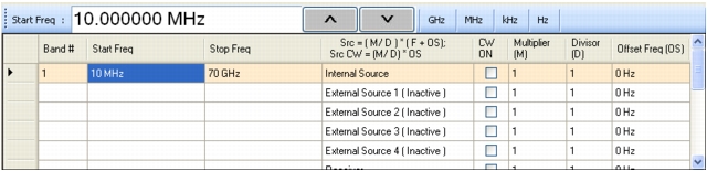
MULTIPLE SOURCE Tableau
The MULTIPLE SOURCE tableau dialog appearance differs slightly depending on the instrument model number and installed options.
Defining a Multiple Source Band
A red exclamation point (!) in the first column of the table indicates that an error is detected.
For each band, the following must be defined:
• A start frequency for the band.
• A stop frequency for the band.
• Equations for each source, the receiver, and receiver source (an index used to work with receiver calibrations). If a source is inactive, its equation may be left at anything. If active, the result of the equation must be a valid frequency for that source (or receiver).
Each equation is of the following form:
(Eq. 17-1)
Using the multiplier (M) and divisor (D), a rational relationship can be created between the desired frequencies. The offset (OS) completes the remainder of the linear relationship and is the CW frequency when the source is set to CW ON. Any of these parameters may be negative as long as the result of the equation is a valid frequency for that source (or receiver). This can be used for a reverse sweep (in certain mixer measurements for example).
When a cell is highlighted in the table (with the mouse or touch screen), the text entry box becomes active. Text can be directly entered into the table by double-clicking on the cell. The entry must be typed with a space between the number and the frequency units.
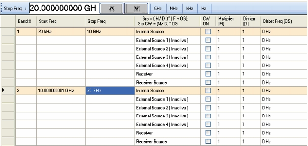
MULTIPLE SOURCE Tableau – Two Band Multiple Source Tableau
The MULTIPLE SOURCE tableau dialog appearance differs slightly depending on the instrument model number and installed options.
As soon as values are changed in the table, the Done Editing button shown in Figure: Main MULTIPLE SOURCE Setup Menu becomes active. Selecting the Done Editing button will start an error check of all entered parameters. An error dialog may appear if an error is found. During the error checking, the system applies the band limit frequencies to each equation and checks that the results are valid for a given source or the receiver. If an external source is inactive, the error checking will not be performed for that line.
Note
The Done Editing button in the Multiple Source menu MUST be clicked for new values to take effect.
Band frequency ranges DO NOT define a required start and stop frequency. These merely set the min and max possible for start and stop. Readjust the desired range for actual measurements on the frequency menu.
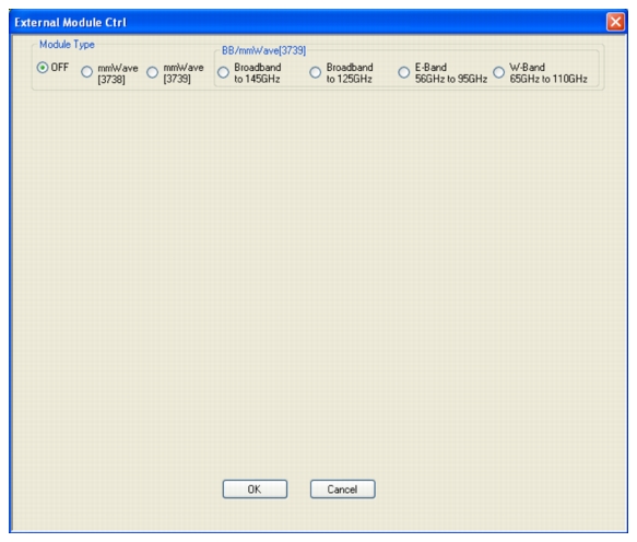
External Module Control
The EXTERNAL MODULE dialog box is accessed off the primary MULTIPLE SOURCE menu.
This dialog box allows the use of a 3738x or 3739x Test Set and external broadband or millimeter-wave modules. The activation is by band and when turned on, the test set will be informed to activate its modules and use current knowledge of the driving port. This would commonly be used for broadband or mm-Wave measurements when the broadband/mm-Wave mode is too restrictive for the desired measurements. This may happen if different IFs are desired, additional frequency converters are involved in the measurement, or other unusual scenarios. The external IF ports are automatically activated in any of the non-Off modes as are leveling and power control schemes associated with the given test set (see Broadband / mm-Wave Measurements (Option 007) for more test set information). Only one global mode can be selected per channel but that external module selection can be activated or de-activated on a band-by-band basis.
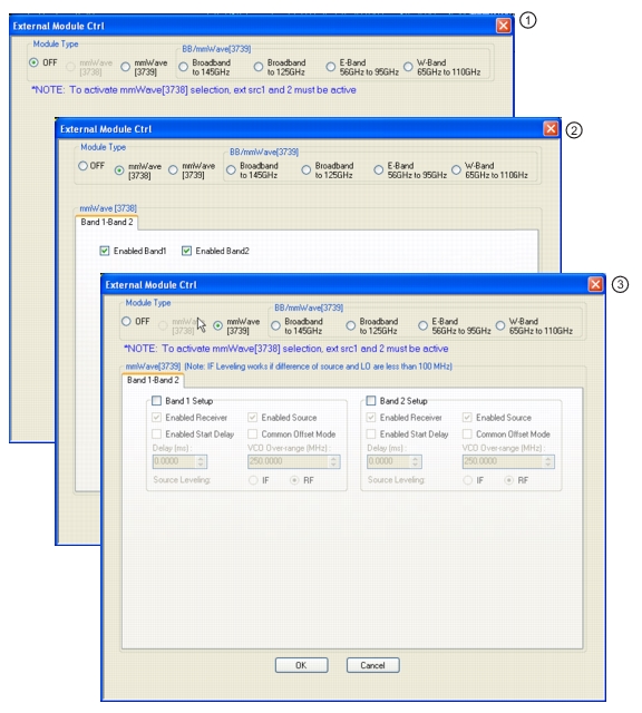
External Module Ctrl = OFF
External mm-wave or broadband test sets are not being used. The dialog in this state is shown in Figure: The external module control dialog box with off selected is shown here.. The 3739x test set does not require external synthesizers, so these non-OFF choices will always be available assuming option 08x is present. The 3738 test set does not require additional options, but does require the presence of external synthesizers 1 and 2 on the GPIB bus.
The external module control dialog box with off selected is shown here.
External Module Ctrl = mm-wave (3738)
The 3738x test set is being used with conventional OEM mm-wave modules (the ME7828 family of systems). In this case, a check box will be available per-defined band to allow activation of the test set in that band. This option is only available if External Sources 1 and 2 are connected and active. There are no other parameters to select other than to activate or de-activate on a band-by-band basis.
As an example to show how this selection might be used, consider a DUT that is a downconverter taking 250 to 300 GHz down to a fixed IF of 1 GHz. The LO is sub-harmonically driven with an effective multiplier of 18 and will be driven from External Source 3 (EXT. SRC 3). The RF is supplied by an external mm-wave module (WR-03 waveguide in this case), which also has an effective source multiplier of 18, and this will be driven from External Source 1 (EXT. SRC. 1). This external module also has an LO input (x20 effective multiplier) that will be driven from External Source 2 (EXT SRC 2). It is desired to measure both return loss (at the RF) of the DUT as well as its conversion loss. This will require two different multiple source setups since the conversion paths in the VNA are different.
Return Loss Measurement
Connect all external synthesizers and make sure the GPIB addresses match, and that 10 MHz clocks are synchronized (or higher frequency references if those are being used). It is desired that the DUT LO port be driven since that can affect return loss. Since the mm-wave module IF outputs will be used (and routed to the VNA rear panel), the Ext Module Ctrl for BB/mm-Wave must be enabled.
• Band 1: 250-300 GHz
• Int Src (Internal Source) = 1/1(CW 3 GHz)
• We are not using the internal source so it is just parked.
• Ext Src1 (External Source) = 1/18(f +0)
• Ext Src2 = 1/20(f+12.35 MHz)
• The system IF (rear panel) is 12.35 MHz.
• Ext Src3 = 1/18(f+ 1 GHz)
• Rcvr (Receiver) = 1/1(CW 2 GHz)
• We are not using the internal LO so this is just parked.
Conversion Loss Measurement
In this case, Ext Module Ctrl must be OFF since we will not be using the rear panel IFs. Note that this also disables the test set so some care is required with RF signal cabling.
• Band 1: 250 to 300 GHz
• Int Src = 1/1(CW 3 GHz)
• We are not using the internal source so it is just parked.
• Ext Src1 = 1/18(f +0)
• Ext Src2 = 1/1 (CW 2 GHz)
• The external mm-wave module LO is not being used.
• Ext Src3 = 1/18(f+ 1 GHz)
• Rcvr = 1/1(CW 1 GHz)
• The DUT IF is routed to a port or receiver loop so it can be converted
External Module Ctrl = mm-wave (3739)
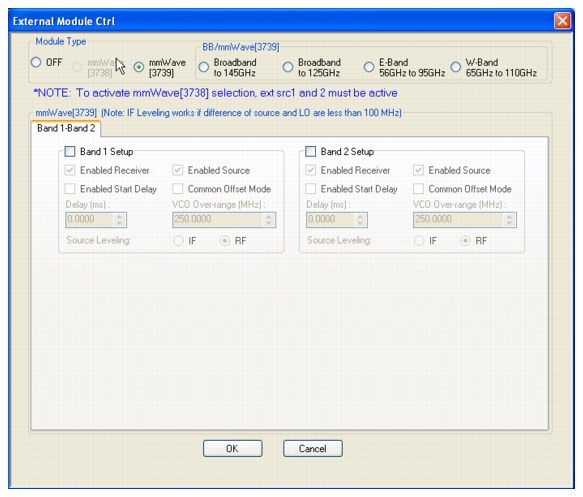
The mm-wave (3739) selection also assumes the use of OEM mm-wave modules, but with the 3739x test set. Details on some applicable modules, from a hardware perspective, are discussed in Broadband / mm-Wave Measurements (Option 007). Any multiplied transceivers can be used here as long as the frequency and power plans are consistent with the VectorStar system with the 3739x test set. The test set offers additional power control options and assumes the use of the internal VNA sources so there are some additional selection options as suggested by Figure: The external module control dialog is shown as configured for a single active band of mm-wave (3739)..
The external module control dialog is shown as configured for a single active band of mm-wave (3739).
The selection choices per band are described below:
• Enabled Receiver: Use the receiver in the remote modules. Above this breakpoint, the VNA system LO will be set appropriately in terms of frequency and power, the test set configured, and the VNA’s rear panel IFs will be activated.
• Enabled Source: Use the source multipliers in the remote modules. When enabled the VNA synthesizers will be set appropriately, the test set configured as needed, and ALC leveling prepared (see below).
• Enabled Start Delay: This enables a fixed delay at the beginning of the band. This could be useful for certain slow settling DUT measurements or for very low power levels.
• Common Offset Mode: At higher multiples (generally for modules running over 300 GHz), it may be desired to improve source correlation to reduce trace noise. This can be done with the Common Offset mode bit (and it is automatically done in the 3739 mm-wave modes discussed in Broadband / mm-Wave Measurements (Option 007)). If the source and receiver frequencies (when reduced to the 2.5-5 GHz range by division) differ by more than about 50 MHz with this bit selected, phase lock errors may occur so this selection is not appropriate for mm-wave mixer measurements but is useful for IMD and other related measurements.
• VCO Over range: Normally, the internal VNA multipliers switch at 5, 10, 20, and 40 GHz. In some mm-wave modules operating with high multipliers, it may be desirable to push those switch points out further (up to 5.5, 11, 22, and 44 GHz typical, but not guaranteed). This overrange (expressed in MHz relative to the 5 GHz breakpoint) sets the new breakpoints.
• Source Leveling: The leveling choice determines which detection path is used (RF implies the VNA detection on the RF drive path, IF uses the test set detection on a reference IF). Additional cals using the mm-wave ALC subsystem may be required. Generally, IF leveling is only valid if the IF coming from the mm-wave modules is under 100 MHz.
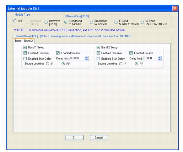
External Module Ctrl= BB/mmWave (3739)
For use with 374x and MA25300A modular components. This right side of the radio button array is for the broadband operation and for banded operation. The selection for BB/mmWave is straightforward. When checked in a given band, the test set will be activated, the VNA’s internal transfer switch will be shut down, and the rear panel IF ports on the VNA will be activated. There are at least three choices: broadband, E-band, or W-band. The distinction between these selections is based on the imposed frequency range limits when activated. Broadband allows from the lower instrument limit up to the upper limit of the system (125 GHz or 145 GHz (150 GHz operational) for ME7838A, and ME7838D systems respectively), E band allows 56-95 GHz (under range to 54.000000001 GHz allowed), and W band allows 65 GHz to 110 GHz. For systems loaded with option 080/081, two broadband buttons will be available for 125 GHz or 145 GHz (operational to 150 GHz) situations. The former should be used if 3743x modules are employed and either can be used if MA25300A modules are in use. The dialog in the case of broadband set for two bands is shown in Figure: The external module control set for broadband (3739x-based) mode is shown here with two bands configured for that mode..
The external module control set for broadband (3739x-based) mode is shown here with two bands configured for that mode.
These MA25300A, 3743x, and 3744x modules have independent source and receiver paths that can be selected from the above dialog. The selections can be interpreted as follows:
• Enabled Receiver: Use the receiver in the remote modules above the receiver breakpoint (30 GHz). Above this breakpoint, the VNA system LO will be set appropriately in terms of frequency and power, the test set configured, and the VNA’s rear panel IFs will be activated.
• Enabled Source: Use the source multipliers in the remote modules above the source breakpoints (54 GHz, 80 GHz, and 120 GHz for x2, x3, and x4 respectively for 3743A modules; 54 GHz, 80GHz, and 110 GHz for x2, x3, x6 for MA25300A modules). Above the first breakpoint, the VNA synthesizers will be set appropriately, the test set configured as needed, and ALC leveling prepared (see below). Note that the above and below 54 GHz power control setting apply when this source feature is enabled.
• Enabled Start Delay: This enables a fixed delay at the beginning of the band. This could be useful for certain slow settling DUT measurements or for very low power levels.
• Source Leveling: The default operation of the modular BB system (when not in multiple source) is to use IF leveling in order to get wide power ranges, but if the source and receiver frequencies are not close enough (or the receiver is not enabled), then an IF is not available for leveling. The leveling defaults to RF in multiple source modular BB and this is recommended unless one knows the IF will be available (up to about 100 MHz) in the module for leveling. Separate ALC calibrations are available for RF and IF leveling and the system will automatically index the correct calibration table.
2. Dialog box with Module Type mmWave (3738) selected. Selection boxes enable Band 1 and/or 2.
3. Dialog box with Module Type mmWave (3739) selected. Selection boxes and control fields enable configuration control of Band 1 and/or Band 2.
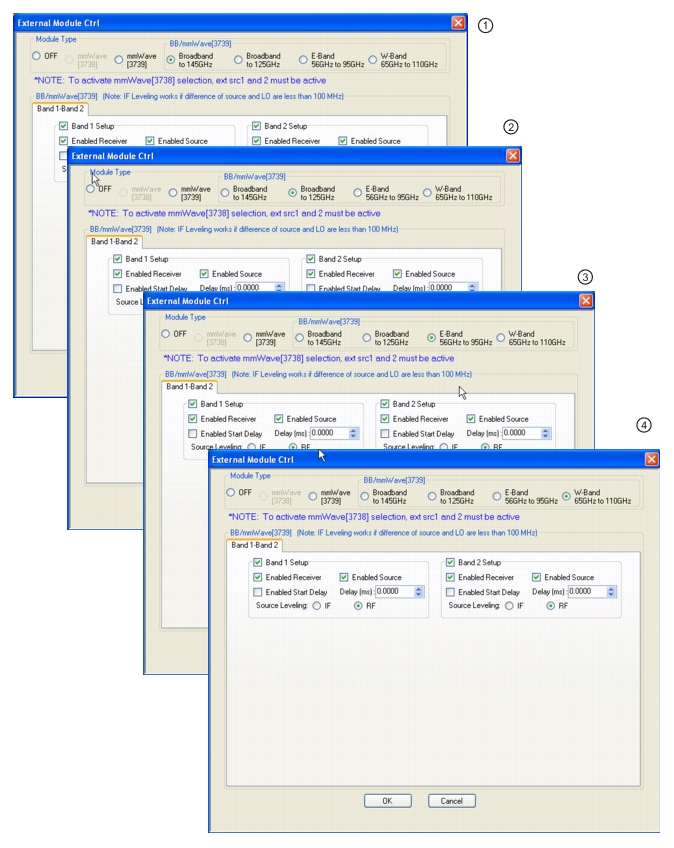
EXTERNAL MODULE CTRL Dialog Box – Broadband, E-Band, and W-Band
1. Dialog box with Module Type Broadband to 145 GHz selected. Selection boxes and control fields enable configuration control of Band 1 and/or Band 2. This module type and mode only available with MS4647A VNAs equipped with Option 08x.
2. Dialog box with Module Type Broadband to 125 GHz selected. Selection boxes and control fields enable configuration control of Band 1 and/or Band 2. This module type and mode only available with MS4647A VNAs equipped with Option 080/081.
3. Dialog box with Module Type E-Band 56 GHz to 95 GHz selected. Selection boxes and control fields enable configuration control of Band 1 and/or Band 2. This module type and mode only available with VNAs equipped with Options 080/081 or 082/083.
4. Dialog box with Module Type W-Band 65 GHz to 110 GHz selected. Selection boxes and control fields enable configuration control of Band 1 and/or Band 2. This module type and mode only available with VNAs equipped with Option 080/081 or 082/083.