Particularly in mixers, it is important to know the relationship between RF and LO frequencies. Consider a down converter:
• LO > RF or High-Side Mixing
Here the IF will have the expected phase behavior for the system and phase inversion is not required.
• LO < RF or Low-Side Mixing
Here the IF will be conjugated by the DUT and the phase behavior will be the inverse of that expected. Phase inversion should be used.
Since the system has no way of knowing which source is the RF and which is the LO, or if additional fixed conversions are occurring, the information must be input manually through the Phase Inversion button on the MULTIPLE SOURCE menu, as shown in Figure: Main MULTIPLE SOURCE Setup Menu above
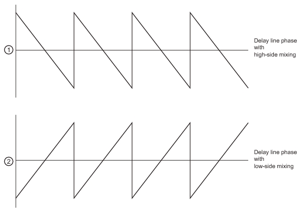
To understand how this affects measurements, consider the phase of a delay line (after normalization with a thru line for example) when high side vs. low side mixing occurred as shown in the 3743X Module Block Diagram in Figure: 3743X Millimeter-Wave Module – Block Diagram of Leveling Options above.
Phase Inversion Behavior
1. Delay line phase with high-side mixing (at top).
2. Delay line phase with low-side mixing (at bottom).
The selection of the phase inversion button reverses the effect seen in low side mixing. The most severe impact can occur in calibrations where line and offset lengths are presumed to impact phase according to equations like (where L is the length and B is the propagation constant):
(Eq. 17-2)
If low side mixing is present, the sign of this equation is incorrect and the calibrations will proceed with the wrong phase values. Proper selection of the phase inversion button will avoid those problems.
Receiver Source and Receiver Calibrations
Although receiver calibrations are covered in more detail in another section of this measurement guide, the special use of a multiple source equation should be discussed here.
The receiver calibration is sufficiently general that it may help perform power normalizations even at the plane of an external converter (acting like a pre-receiver). This receiver may be well-characterized at its frequency range (different from the frequency range of the MS4640A Series VNA receiver) but there must be some means of looking up the correct value in that characterization. This is the purpose of the receiver source equation: to act as an index to a receiver calibration that may refer to an unusual reference plane. In most common cases, the receiver source equation is just set equal to the receiver equation. If receiver calibrations are not in use, this equation can be set to any valid frequency.