VectorStarâ„¢ MS4640A Series Microwave Vector Network Analyzers : Mixer Setup and Measurement : Active Channel Mixer Guided Setup Controls
 
Active Channel Mixer Guided Setup Controls
The guided setup and wizard sections of the application menu are split into two parts: one that only sets up the active channel and acts more as a guide (will be discussed now) and a multi-channel wizard that helps one configure multiple measurements in a more organized fashion (to be discussed later in this chapter). Details on the controls themselves are covered in the operations and user interface manuals. The purpose here is to discuss how the controls relate to the mixer measurement concepts discussed previously.
The basic setup screens for this active channel method are shown in Figure: Mixer Setup Dialogs. The IF and RF ports can be assigned to different VNA physical ports as has been discussed and the IF/RF labeling can be swapped (see the check box near the top). Both frequency sweeps (of input and LO possibly) and power sweeps are supported and are chosen from a pull-down menu. Also part of the input/output duality is how the x-axis of the plots are labeled and this is handled by the pull-down in the lower left part of the dialog. In the case of a fixed output frequency or a fixed input frequency, labeling the x-axis with the fixed variable is usually not helpful.
Mixer Setup Dialogs
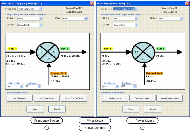
1. On left, MIXER SETUP (FREQUENCY SWEEP).
2. On right, MIXER SETUP (POWER SWEEP).
 
The frequency ranges (including the possibility of reverse sweeps) are shown in the dialog and are setup using a sub-dialog as shown in Figure: Frequency Setup Dialog for Frequency-Sweep Case. The conversion direction and sideband choices discussed previously are handled here and there are many permutations possible. The conversion direction is selected from the radio buttons at the bottom and note the two downconversion selections discussed previously (USB and LSB). Input, output, or LO may be fixed (generally only one of them) and an Auto selection may be used to let the system calculate the frequencies for one of the ports. It is, of course, possible, for an invalid frequency combination to be entered (out of range of the hardware) but this will be scanned for when the OK button is selected.
 
Frequency Setup Dialog for Frequency-Sweep Case
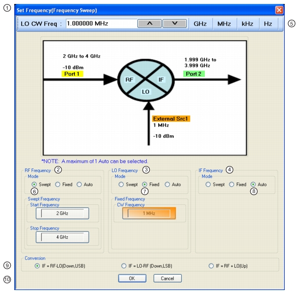
1. SET FREQUENCY (FREQUENCY SWEEP) Wizard Dialog Box.
2. RF Frequency mode and value area.
3. LO Frequency mode and value area.
4. IF Frequency mode and value area.
5. Frequency input field toolbar. The label changes depending whether RF, IF, or LO are selected.
6. Mode set as Swept. Any combination of the RF, IF, and LO ports can be set as Swept. When selected, Start and Stop Frequency fields appear.
7. Mode set as Fixed. Any combination of the RF, IF, and LO ports can be set as Fixed. When selected, a CW Frequency field appears.
8. Mode set as Auto. Only one of the three ports can be set as Auto. If selected, the instrument determines the frequency settings based on the other two values and the Conversion type setting.
9. Conversion setting. Changes based on whether RF is input or output.
10. Dialog box control buttons.
 
In the case of a power sweep, all of the frequencies must be CW so the frequency selection dialog simplifies as shown in Figure: Frequency Setup Dialog for Power Sweep Case. The same sideband and conversion choices apply; there is just no frequency sweeping involved in this measurement setup.
Frequency Setup Dialog for Power Sweep Case
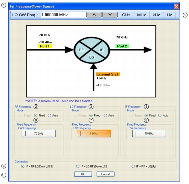
1. SET FREQUENCY (POWER SWEEP) Dialog Box.
2. RF Frequency mode and value area.
3. LO Frequency mode and value area.
4. IF Frequency mode and value area.
5. Frequency input field toolbar. The label changes depending whether RF, IF, or LO are selected.
6. RF Mode setting can only be Fixed or Auto. Only one mixer port can be Auto. If fixed, RF CW frequency is input in field below.
7. LO Mode setting can only be Fixed or Auto. Only one mixer port can be Auto. LO CW frequency is input in field below.
8. IF Mode setting can only be Fixed or Auto. Only one mixer port can be Auto. IF CW frequency is input in field below.
9. Conversion setting. Changes based on whether RF is input or output. If RF is input, equations show conversion calculations for IF. If IF is input, equations show conversion calculations for RF.
10. Dialog box control buttons.
Correspondingly, the power setup is now more detailed as suggested by Figure: Power Setup Dialog for the Power Sweep Case. There are no conversion complications but there could be simultaneous sweeping of power on input and LO (not commonly done but possible). The swept power input is often done to look at gain compression of the DUT while LO power sweeps are often employed to look at the saturability of the LO path. The latter can be important since it has many linearity implications depending on the DUT technology.
Power Setup Dialog for the Power Sweep Case
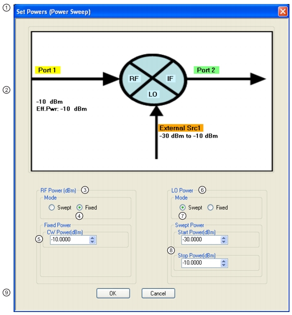
1. SET POWERS (POWER SWEEP) Wizard Dialog Box
2. Mixer Schematic – Port assignments and power levels are updated automatically.
3. RF Power (dBm) controls.
4. RF Power Mode set as Fixed with option of Swept.
5. RF Power CW Power input field
6. LO Power controls
7. Mode set as Swept with option of Fixed.
8. Swept start and stop power input fields.
9. Dialog box control buttons.