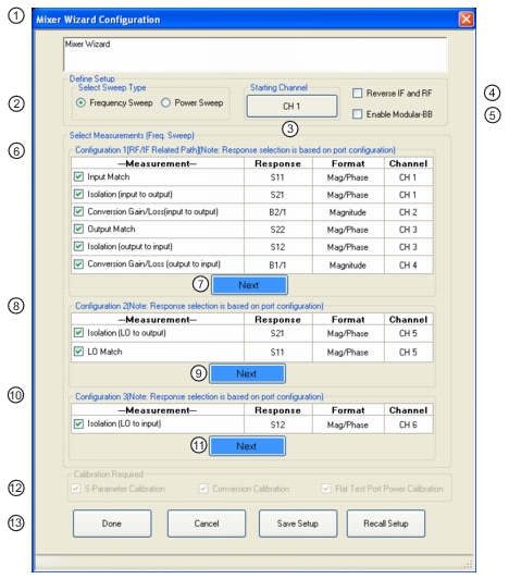
The multiple channel mixer wizard is, in some sense, a natural extension of the single channel setup method introduced previously. The difference here is that multiple measurements are orchestrated for the user in different channels with the corresponding sweeps already setup and the calibrations suggested. The main configuration dialog is shown in Figure: Main Wizard Setup Dialog for Frequency Sweep Case. In addition to some of the controls discussed previously are a list of possible measurements separated into 3 groups: between input and output, between LO and output, and between LO and input. The three groups require different connections since the LO port needs access to receivers in the second two sets. All measurements can be setup at once but the results from different groups will only be meaningful if the DUT is connected correctly
2. Select Sweep Type as Frequency Sweep or Power Sweep.
3. Channel Start Selection
4. Reverse IF and RF – Default is RF as input and IF as output. Toggles to RF as output and IF as input.
5. Enable Modular-BB – Only for MS4647A VNAs with Option 080/081 BB/m-Wave System.
6. Configuration 1 – Conversion Gain/Loss Swept LO – RF/IF Related Path – Select any combination of measurements. Channels are automatically assigned based on Starting Channel.
7. Next Button – Links to Configuration 1 Dialogs to configure mixer and VNA ports, external sources, frequency, and power levels.
8. Configuration 2 – Compression Pout versus Pin Swept RF – Select any combination of measurements. Channels are automatically assigned.
9. Next Button – Links to Configuration 2 Dialogs to configure mixer and VNA ports, external sources, frequency, and power levels.
10. Configuration 3 – Isolation – LO to Input Available Measurement
11. Next Button – Links to Configuration 3 Dialogs to configure mixer and VNA ports, frequency, and power.
12. Calibration Required Area
13. Dialog Controls
All of the measurements shown have been discussed previously but now they are automatically assigned to different channels that will control the different sweeps. To see this concept, suppose one requests forward conversion gain/loss (input to output), isolation (input to output) and isolation output to input. The first measurement requires the source to sweep over the input frequencies while the receiver sweeps over the output frequencies. The second measurement requires both the source and receiver to sweep over the input frequencies. The third measurement requires both the source and receiver to sweep over the output frequencies. By placing these three measurements in different channels, all the measurements can be completed in one ‘super sweep’ without user intervention and all of the results displayed at once.
There is a ‘starting channel’ button on this dialog to indicate which channel should have the first measurement and the others will increment from there. While the default is to start with channel 1, the user may have setups in one or more channels that they would like to keep sweeping in addition to those measurement orchestrated by the mixer wizard.
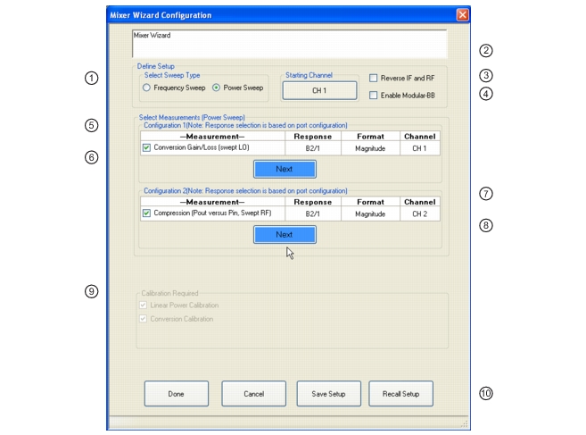
The power and frequency setup dialogs are essentially the same as for the single channel setup system and will not be repeated here. Minor differences can be analyzed in the operating manual or the UI guide. For the power sweep case, the choices are more limited and are shown in Figure: Main Wizard Setup for Power Sweep Case. As had been discussed previously, conversion gain as a function of input power (compression) may be of interest as can conversion gain versus LO power (looking for LO saturation while the input power is constant). Unlike the manual method in the single channel setup, here the swept power on the respective port will be requested.
Main Wizard Setup for Power Sweep Case
1. Select Sweep Type
2. Select Starting Channel
3. Reverse RF and IF – Standard is RF is input and IF output. Reverse is RF as output and IF as input.
4. Enable Modular Broadband.
5. Configuration 1 Measurements for Conversion Gain/Loss Swept LO.
6. Next button to Configuration 1 dialogs
7. Configuration 2 Measurements for Compression Pout versus Pin Swept RF.