This section describes eight programs that demonstrate the use of the 37XXX LabVIEW driver controlling the MS4640A Series VNA. The programs provide functions to:
• Open a session
• Send the *IDN? command
• Check for errors
• Send data to a file with the LIST command
• Acquire trace data
• Acquire Smith Chart data
• Output an S2P File
• Output a BMP file
Setup Communications
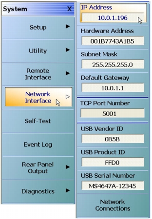
1. Set up VXI-11 (TCP/IP) communications by noting the IP Address of the VNA and set up a resource (a connection string).
MS4640A Series VNA IP Address
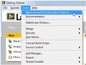
2. Set up the VISA resource using the Measurement and Automation Explorer (MAX).
LabView Tools
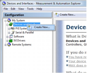
3. Create a new resource in MAX by right clicking Devices and Interfaces and select Create New.
Measurement and Automation Explorer (MAX)
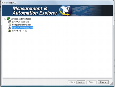
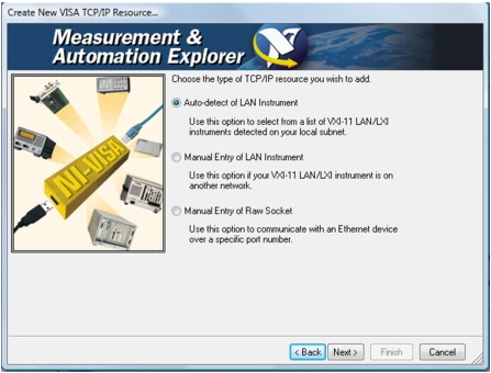
4. Select the VISA TCP/IP Resource.
Create New Resource Dialog
5. If the controlling PC and the VNA are on the same local sub-network (this is usually true if the first 3 numbers in the IP address are the same – for example, 10.0.1.x in this case), then you can Auto-detect the VNA. Otherwise, you need to manually enter the IP address.
Create New VISA TCP/IP Resource Dialog
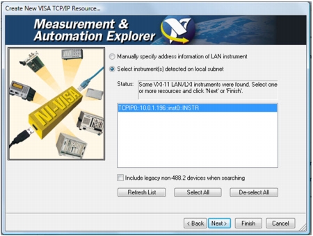
6. Select the detected instrument.
Create New VISA TCP/IP Resource Dialog
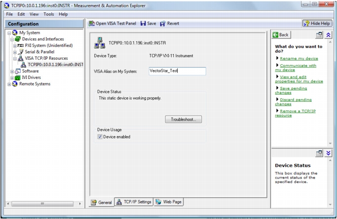
7. Give the instrument an alias (the VectorStar_Test alias is used in LabVIEW).
Measurement and Automation Explorer (MAX)
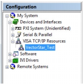
8. Note that the VISA connection string has been replaced with the VISA alias.
Measurement and Automation Explorer Configuration
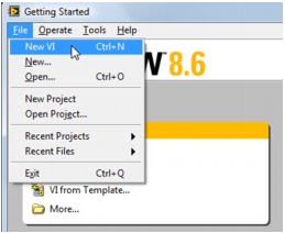
9. In LabVIEW, begin creating the first example, a New VI.
LabVIEW New VI
Example 1 – Opening a Session
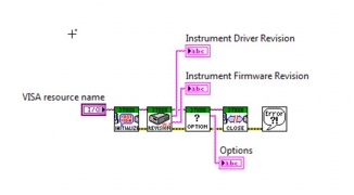
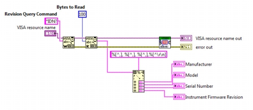
In this first example, a communication session is opened to the VNA and two of the driver VIs are used to get some information about the VNA. The block diagram below shows four VIs from the Anritsu 37XXX Series driver:
• Initialize.vi
• Revision Query.vi
• Instrument Options.vi
• Close.vi.
VI Block Diagram
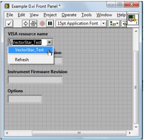
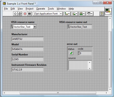
1. In the Front Panel dialog, select “VectorStar_Test”, which was set up previously, as the VISA resource name.
Front Panel Dialog
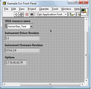
2. After running this VI, the Instrument Driver Version, Instrument Firmware Version, and Options are filled in.
Front Panel Dialog
Example 2 – Sending the *IDN? Command
The previous example used only driver VIs to get some information from the VNA. The GPIB command, “*IDN?” returns the Manufacturer, Model #, Serial Number and Firmware Version. In this example, the “*IDN?” command is used directly and the return string is parsed into the different parts of the response.
1. Directly send a GPIB string using the VISA Write function, then read the response from the VNA using the VISA Read function.
VI Block Diagram
2. Use the Scan From String function to grab the different comma-separated values in the response string.
Front Panel for Example 1
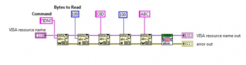
Example 2 – Error Checking
Most of the 37xxx driver VIs use the Error Query.vi. This example shows that if an invalid GPIB string is sent to the VNA, then the Error Query VI catches the error and displays the error message from the VNA.
1. Two valid strings, “*IDN?” and “OID,” are sent, but the third string is not a valid GPIB command and the instrument reports this to the Front Panel.
2. Mix VISA Writes and Reads with the 37XXX driver’s Error Query VI.
VI Block Diagram
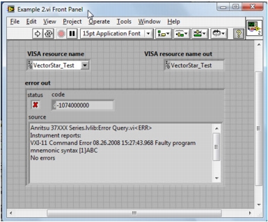
3. The “ABC” command sent is invalid and was captured by the Error Query VI.
Front Panel for Example 2
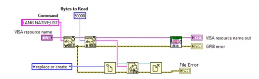
Example 3 – Sending Data to a File with the LIST Command
This example sends output to a file that the user may specify (a file dialog is opened). The VISA Write command is used to send the LIST command to the VNA. The “LANG NATIVE” command is used because this sends a newline after each command in the output. If “LANG LIGHT” is used, then the commands are separated by a comma and the file is more difficult to read.
VI Block Diagram
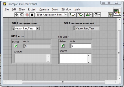
The Front Panel shows that no errors were produced with either the GPIB code or with the File writing code.
Front Panel for Example 3
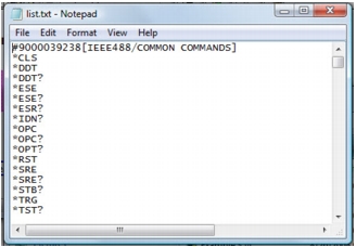
The List of all commands supported by the MS4640A Series VNA is output to a text file. Note that the first line has an arbitrary block header, which is covered in Example 6.
Command List
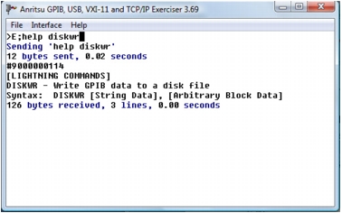
Use the Anritsu GPIB, USB, VXI-11, and TCP/IP Exerciser to get more help on any command. Help displays the type of command (Lightning, Native, or HP8510) and provides syntax.
Anritsu GPIB, USB, VXI-11, and TCP/IP Exerciser
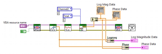
Example 4 – Acquiring Trace Data
Trace 2 is set to Log magnitude and Phase data and the data comes out in a one dimensional interleaved array. The array must be parsed to get the data into two separate arrays. In this example, the VNA is initialized to get Log Magnitude and Phase Data (Final Data) from Trace 2. When two sets of data exist, the 1D array must be parsed into two arrays since data 0, 2, 4, etc., is Log Magnitude data and data 1, 3, 5, etc., is phase data.
VI Block Diagram
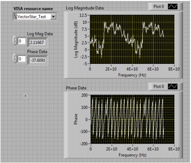
Send separate traces to each XY Graph. (Note that this data is from a simulated MS4640A and might not look authentic).
Front Panel for Example 4
Example 5 – Smith Chart Data
This example is similar to the previous example except the instrument is not reset, which sets up smith charts on trace 1 and 4. Although the frequency data is not needed to display the smith chart, the frequency list is extracted from the Read Frequency Values VI and the data count is determined from the number of frequencies. This data count is passed to the For Loop control.
By default Trace1 is set to output impedance values. Smith chart takes a normalized impedance (normalized to 1), so we divide the impedance/reactance pairs by 50 (ohms) to get normalized smith chart data.
Use the Frequency Array to get the number of points to input into the For Loop control. The Channel Data from Channel 1 is Impedance/Reactance, so divide by Z0 (or 50 ohms, hardcoded here) to get the smith chart data.
VI Block Diagram
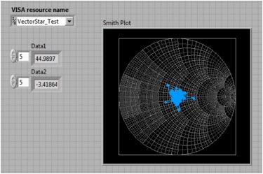
Below is the Front Panel Display where the data is from a simulated MS4640A.
Front Panel for Example 5
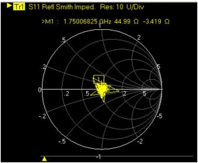
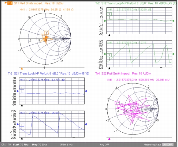
Below is the equivalent display on the MS4640A.
MS4640A VNA Smith Chart Display
Example 6 – Output S2P File
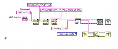
This example uses VISA Writes and 37XXX driver VIs to accomplish tasks that the driver can’t perform. Specifically, sending Native MS4640A commands with Lightning commands to output an S2P file from the VNA to the PC. Since the driver VI is saved as a Private VI in the version 1.1 driver it must be made public (as shown in Figure: Project Explorer).
A combination of VISA and driver commands is used to first send Native GPIB strings to setup the S2P output to 25 data points, Frequency in Hz, and Data Format to Real/Imaginary via the Read ASCII ARB function (the private driver to be made public, and then included directly to the VI).
VI Block Diagram
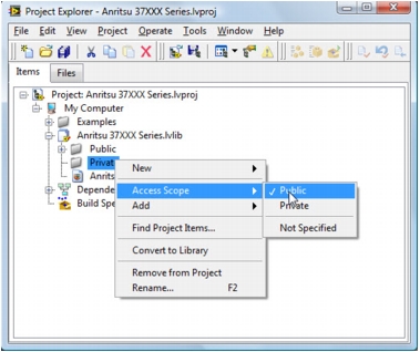
Several of the Private functions in the driver are useful and can be made public by using Access Scope in the Project Explorer.
Project Explorer
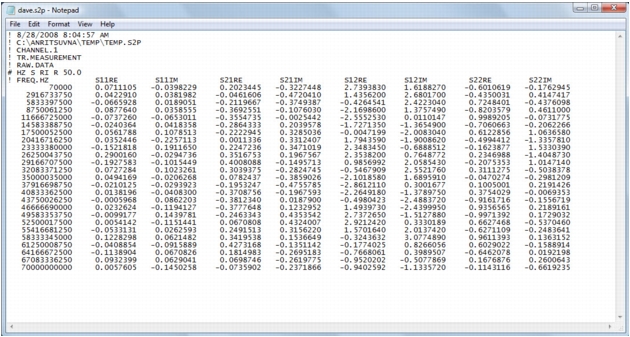
When the VI runs, a dialog allows the transferred S2P file name to be selected. Make sure to save the file with an “.S2P” extension.
S2P File
Example 7 – Output BMP File
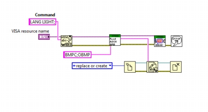
A similar technique as that used in example 6 gets the bitmap data to a file. The Lightning commands “BMPC;OBMP” outputs a bitmap file. BMPC selects color on white as the color scheme, making for better printouts. The “Read ASCII ARB.vi” is used to strip off the arbitrary block header and place the bitmap data into a file (the header corrupts the bitmap file).
VI Block Diagram
When the VI runs, a dialog allows the file name to be selected. Make sure to save the file with a “.bmp” extension.