The IEEE 488 General Purpose Interface Bus (GPIB) is an instrumentation interface for integrating instruments, computers, printers, plotters, and other measurement devices into systems. The interface between the VectorStar VNA and other devices on the GPIB is via a standard 24-wire GPIB interface cable. This cable uses a double-sided connector where one connector face is a plug and the other a receptacle. These double-function connectors allow parallel connection of two or more cables to a single instrument connector.
Caution
When two or more cables are connected in parallel, you must be careful not bend the attached connectors and damage the rear panel GPIB Port connector.
GPIB Network Restrictions
To achieve design performance on the GPIB network bus, the proper timing and voltage level relationships must be maintained. If either the cable length between separate instruments or the accumulated cable length between all instruments is too long, the data and control lines cannot be driven properly and the system may fail to perform.
• Network Topology
GPIB network topologies can be in any combination of star and/or serial (“daisy-chain”) network topology subject to the limitations below. Looped topologies are prohibited. If a star topology is used, care must be observed when stacking two or more GPIB connectors.
• Number of Units
The maximum number of physical GPIB devices must be less than or equal to 15 including the controller.
• Addresses
The default address for a GPIB Controller Device must be 0 (zero). The address for a GPIB-controlled device can be from 1 (one) to 30. Each device address in a GPIB network must be unique.
• Total Network Length
The network length is measured in meters. The total network length of all cables less than two times the number of instruments, and always less than 20 meters. For example, the maximum length of a 2 instrument network is 4 meters; a 6 instrument network is limited to 12 meters; and networks of 10 or more instruments are limited to 20 meters.
• Maximum Network Leg Length
The recommended length of any network leg is less than or equal to 4 meters. In all cases, minimize cable lengths to achieve maximum data transfer rates.
• Power State
Two-thirds of the network devices must be powered on before signaling is started. No devices should be powered up while bus signaling is in operation where devices are actively sending or receiving messages or data.
Note
For low EMI applications, the GPIB cable should be a fully shielded type with well-grounded metal-shell connectors. Use Anritsu Model 2100-series cables.
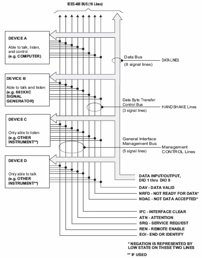
The devices on the GPIB are connected in parallel, as shown in Figure: GPIB Interface Connection and Bus Structure. The interface consists of 16 signal lines and 8 ground lines in a shielded cable. Eight of the signal lines are the data lines, DIO 1 through DIO 8. These data lines carry messages (data and commands), one byte at a time, among the GPIB devices. Three of the remaining lines are the handshake lines that control the transfer of message bytes between devices. The five remaining signal lines are referred to as interface management lines.
The following paragraphs provide an overview of the GPIB including descriptions of:
Effective communications between devices on the GPIB requires three functional elements; a talker, a listener, and a controller. Each device on the GPIB is categorized as one of these elements depending on its current interface function and capabilities.
• Talker
A talker is a device capable of sending device-dependent data to another device on the bus when addressed to talk. Only one GPIB device at a time can be an active talker.
• Listener
A listener is a device capable of receiving device-dependent data from another device on the bus when addressed to listen. Any number of GPIB devices can be listeners simultaneously.
• Controller
A controller is a device, usually a computer, capable of managing the operation of the GPIB. Only one GPIB device at a time can be an active controller. The active controller manages the transfer of device-dependent data between GPIB devices by designating who will talk and who will listen.
• System Controller
The system controller is the device that always retains ultimate control of the GPIB. When the system is first powered-up, the system controller is the active controller and manages the GPIB. The system controller can pass control to a device, making it the new active controller. The new active controller, in turn, may pass control on to yet another device. Even if it is not the active controller, the system controller maintains control of the Interface Clear (IFC) and Remote Enable (REN) interface management lines and can thus take control of the GPIB at anytime.
Bus Structure
The GPIB uses 16 signal lines to carry data and commands between the devices connected to the bus. The interface signal lines are organized into three functional groups.
Data Available Not Ready For Data Not Data Accepted
General Interface Management Bus
ATN IFC SRQ REN EOI
Attention Interface Clear Service Request Remote Enable End Or Identify
Data Bus Description
The data bus is the conduit for the transfer of data and commands between the devices on the GPIB. It contains eight bidirectional, active-low signal lines —DIO 1 through DIO 8. Data and commands are transferred over the data bus in byte-serial, bit-parallel form. This means that one byte of data (eight bits) is transferred over the bus at a time. DIO 1 represents the least-significant bit (LSB) in this byte and DIO 8 represents the most-significant bit (MSB). Bytes of data are normally formatted in seven-bit ASCII (American Standard Code for Information Interchange) code. The eighth (parity) bit is not used.
Each byte placed on the data bus represents either a command or a data byte. If the Attention (ATN) interface management line is TRUE while the data is transferred, then the data bus is carrying a bus command which is to be received by every GPIB device. If ATN is FALSE, then a data byte is being transferred and only the active listeners will receive that byte.
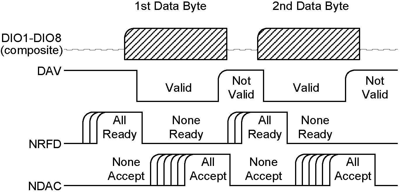
Typical GPIB Handshake Operation
Data Byte Transfer Control Bus Description
Control of the transfer of each byte of data on the data bus is accomplished by a technique called the “three-wire handshake”, which involves the three signal lines of the Data Byte Transfer Control Bus. This technique forces data transfers at the speed of the slowest listener, which ensures data integrity in multiple listener transfers. One line (DAV) is controlled by the talker, while the other two (NRFD and NDAC) are wired-OR lines shared by all active listeners. The handshake lines, like the other GPIB lines, are active low. The technique is described briefly in the following paragraphs and is depicted in Figure: Typical GPIB Handshake Operation. For further information, refer to the ANSI/IEEE Standard 488.1 specification.
General Interface Management Bus Description
The general interface management bus is a group of five signal lines used to manage the flow of information across the GPIB. A description of the function of each of the individual control lines is provided below.
• ATN (Attention)
The active controller uses the ATN line to define whether the information on the data bus is a command or is data. When ATN is TRUE (low), the bus is in the command mode and the data lines carry bus commands. When ATN is FALSE (high), the bus is in the data mode and the data lines carry device-dependent instructions or data.
• EOI (End or Identify)
The EOI line is used to indicate the last byte of a multi byte data transfer. The talker sets the EOI line TRUE during the last data byte. The active controller also uses the EOI line in conjunction with the ATN line to initiate a parallel poll sequence.
• IFC (Interface Clear)
Only the system controller uses this line. When IFC is TRUE (low), all devices on the bus are placed in a known, quiescent state (unaddressed to talk, unaddressed to listen, and service request idle).
• REN (Remote Enable)
Only the system controller uses this line. When REN is set TRUE (low), the bus is in the remote mode and devices are addressed either to listen or to talk. When the bus is in remote and a device is addressed, it receives instructions from the GPIB rather than from its front panel. When REN is set FALSE (high), the bus and all devices return to local operation.
• SRQ (Service Request)
The SRQ line is set TRUE (low) by any device requesting service by the active controller.
Device Interface Function Capability
An interface function is the GPIB system element which provides the basic operational facility through which a device can receive, process, and send messages. Each specific interface function may only send or receive a limited set of messages within particular classes of messages. As a result, a set of interface functions is necessary to achieve complete communications among devices on the GPIB.
The ANSI/IEEE Standard 488.1 specification defines each of the interface functions along with its specific protocol. The ANSI/IEEE Standard 488.2 specification specifies the minimum set of IEEE 488.1 interface capabilities that each GPIB device must have. This minimum set of interface functions assures that the device is able to send and receive data, request service, and respond to a device clear message. Table: VectorStar VNA Interface Function Capability lists the interface function capability of the VectorStar Series VNA.
VectorStar VNA Interface Function Capability
Function Identifier
Function
VectorStar VNA Capability
AH1
Acceptor Handshake
Complete Capability
SH1
Source Handshake
Complete Capability
T6
Talker
No Talk Only (TON)
L4
Listener
No Listen Only (LON)
SR1
Service Request
Complete Capability
RL1
Remote/Local
Complete Capability
PP1
Parallel Poll
Complete Capability
DC1
Device Clear
Complete Capability
DT1
Device Trigger
Complete Capability
C0 C1 C2 C3 C28
Controller Capability Options
C0, No Capability C1, System Controller C2, Send IFC and Take Charge C3, Send REN C28, Send IF Messages
E2
Tri-State Drivers
Three-state bus drivers
Message Types
There are three types of information transmitted over the GPIB:
• interface function messages
• device-specific commands, and
• data and instrument status messages.
Interface Function Messages
The controller manages the flow of information on the GPIB using interface function messages, usually called commands or command messages. Interface function messages perform such functions as initializing the bus, addressing and unaddressing devices, and setting device modes for remote or local operation.
There are two types of commands: multiline and uniline. Multiline commands are bytes sent by the active controller over the data bus (DIO1-DIO8) with ATN set TRUE. Uniline commands are signals carried by the individual interface management lines.
The user generally has control over these commands; however, the extent of user control depends on the implementation and varies with the specific GPIB interface hardware and software used with the external controller.
Device-Specific Commands
These commands are keywords or mnemonic codes sent by the external controller to control the setup and operation of the addressed device or instrument. The commands are normally unique to a particular instrument or class of instruments and are described in its documentation. Device-specific commands are transmitted over the data bus of the GPIB to the device in the form of ASCII strings containing one or more keywords or codes. They are decoded by the device’s internal controller and cause the various instrument functions to be performed.
Data and Instrument Status Messages
These messages are sent by the device to the external controller via the GPIB. They contain measurement results, instrument status, or data files that the device transmits over the data bus in response to specific requests from the external controller. The contents of these messages are instrument specific and may be in the form of ASCII strings or binary data. In some cases data messages will be transmitted from the external controller to the device. For example, messages to load calibration data.
An SRQ (service request) is an interface function message sent from the device to the external controller to request service from the controller, usually due to some predetermined status condition or error. To send this message, the device sets the SRQ line of the General Interface Management Bus true, then sends a status byte on the data bus lines.
An SRQ interface function message is also sent by the device in response to a serial poll message from the controller, or upon receiving an Output Status Byte(s) command from the controller. The protocols associated with the SRQ functions are defined in the ANSI/IEEE Std 488.2 document.
The manner in which interface function messages and device-specific commands are invoked in programs is implementation specific for the GPIB interface used with the external controller. Even though both message types are represented by mnemonics, they are implemented and used in different ways.
Normally, the interface function messages are sent automatically by the GPIB driver software in response to invocation of a software function. For example, to send the IFC (Interface Clear) interface function message, one would call the ibsic function of the National Instruments software driver. On the other hand, the command *RST (Reset) is sent in a command string to the addressed device. In the case of the National Instruments example, this would be done by using the ibwrt function call.
Response to GPIB Interface Function Messages
Table: VectorStar VNA Response to GPIB Interface Function Messages lists the GPIB interface function messages that the MS4640A will recognize and respond to. With the exception of the Device Clear and Selected Device Clear messages, these messages affect only the operation of the VectorStar VNA GPIB interface. The VNA response for each message is indicated below. Interface function messages are transmitted on the GPIB data lines and interface management lines as either unaddressed or addressed to receive the commands. The manner in which these messages are invoked in programs is implementation dependent. For more programming information, refer to the documentation included with the GPIB interface used for the external controller and to the IEEE 488.1 specification.
VectorStar VNA Response to GPIB Interface Function Messages
Interface Function Message
Addressed Command
VectorStar VNA Response
Device Clear (DCL) Selected Device Clear (SDC)
No Yes
Clears the input and output buffers and resets the parser.
Go To Local (GTL)
Yes
Returns the VNA to local front panel control.
Group Execute Trigger (GET)
Yes
In step sweep, single trigger: triggers a sweep. In list sweep, manual trigger: triggers step to next index within start/stop index boundaries. In list sweep, single trigger: triggers a sweep.
Interface Clear (IFC)
No
Stops the VNA GPIB interface from listening or talking. (The front panel controls are not cleared.)
Local Lockout (LLO)
No
Disables the front panel menu RETURN TO LOCAL soft-key.
Remote Enable (REN)
No
Places the VNA under remote (GPIB) control when it has been addressed to listen.
Serial-Poll Enable (SPE)
No
Outputs the serial-poll status byte.
Serial-Poll Disable (SPD)
No
Disables the serial-poll function.
Parallel-Poll Configure (PPC)
Yes
The VectorStar VNA does not respond to Parallel-Poll messages.
Parallel-Poll Unconfigure
No
The VectorStar VNA does not respond to Parallel-Poll messages.
Configuring the Dedicated GPIB Port
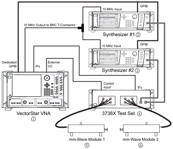
Use this procedure to setup the dedicated GPIB port to control other GPIB devices such as Power Meters or Signal Generators by using the VNA rear panel Dedicated GPIB Port. An example of a complex GPIB configuration with the VNA as the GPIB controller is shown in Figure: VNA as a Remote GPIB Controller for Synthesizers.
VNA as a Remote GPIB Controller for Synthesizers
1. VectorStar VNA
2. Synthesizer #1
3. Synthesizer #2
4. 3738X Broadband Test Set
5. Millimeter-Wave (mm-Wave) Module #1
6. mm-Wave Module #2
Note
For the 68xxx and 69xxx series of external sources, please upgrade them with firmware version 3.39 or higher to ensure they are compatible with the VectorStar software.
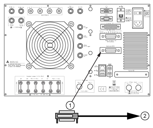
1. Connect GPIB devices to the VNA rear panel Dedicated GPIB Port using the appropriate length GPIB cable.
2. GPIB Cable and Connector: GPIB cable and double-sided connector. Cable routes to any controlled GPIB devices.
2. Power-up the VectorStar VNA and any attached GPIB devices, and allow the system to warm up.
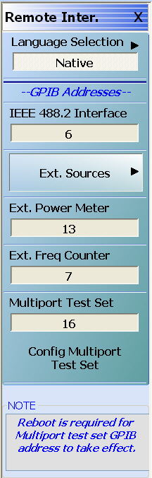
3. Navigate to the Remote Inter. menu as follows:
MAIN | System > | SYSTEM | Remote Interface > | REMOTE INTER/
.
REMOTE INTERFACE (REMOTE INTER) Menu
The GPIB address for any controlled device can be kept at the factory default values or changed as required. The default GPIB addresses are:
• VectorStar MS4640A Series VNA = 6
• VectorStar MN4690B Series Test Set = 16
• External Source 1 = 4
• External Source 2 = 5
• External Source 3 = 2
• External Source 4 = 3
• Power Meter = 13
• Frequency Counter = 7
• W-Band Power Meter = 15
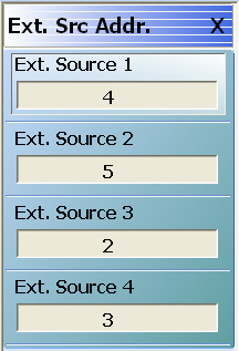
The GPIB addresses for the External Sources can be changed from the Ext Src Addr sub-menu available at:
• MAIN | System | SYSTEM | Remote Interface | REMOTE INTER | Ext Sources | EXT SRC ADDR.
EXT SRC ADDR (EXTERNAL SOURCE ADDRESS) Menu
4. If a change of GPIB address is required, click the device button, and the device field toolbar appears as shown below:
5. Use the front panel keys, a keyboard, or mouse to set the required GPIB address.
6. Click the Enter button to set the new GPIB address.
Configuring the IEEE 488.2 GPIB Port
Use this procedure to set up the talker/listener port to control the VNA remotely over an IEEE 488.2 GPIB bus network. In this configuration, an external computer/controller is physically connected to the VNA rear panel IEEE 488.2 GPIB Port with a standard GPIB cable. Most of the VectorStar VNA functions (except power on/off and initialization of the hard disk) can be controlled remotely by an external computer/controller via the IEEE-488.2 GPIB bus network.
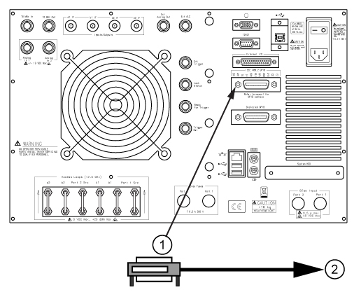
1. Connect the VNA to the GPIB Controller using the rear panel IEEE 488.2 GPIB Port DB-24 (f) connector and a standard GPIB cable.
IEEE 488.2 GPIB Talker/Listener Port and GPIB Cable Connection
2. GPIB Cable and Connector: GPIB cable and double-sided connector. Cable routes to the GPIB Controller computer.
2. Apply power to the VectorStar VNA and allow the system to warm up.
Once the software has finished loading and start-up testing is complete, the instrument is ready to be remotely controlled via the GPIB. The instrument will not respond to GPIB commands until the instrument’s software has been loaded.
Note
The factory default GPIB address for the instrument is six (6).
To change the VectorStar VNA GPIB address:
1. Navigate to the REMOTE INTER menu:
MAIN | System | SYSTEM | Remote Interface | REMOTE INTER
2. On the Remote Inter. menu, the IEEE 488.2 GPIB button.
The IEEE 488.2 GPIB toolbar appears below the icon toolbar near the top of the display.
3. Use the front panel keys, a keyboard, or a mouse to set the required GPIB address.
4. Click the Enter button to set the new GPIB address.