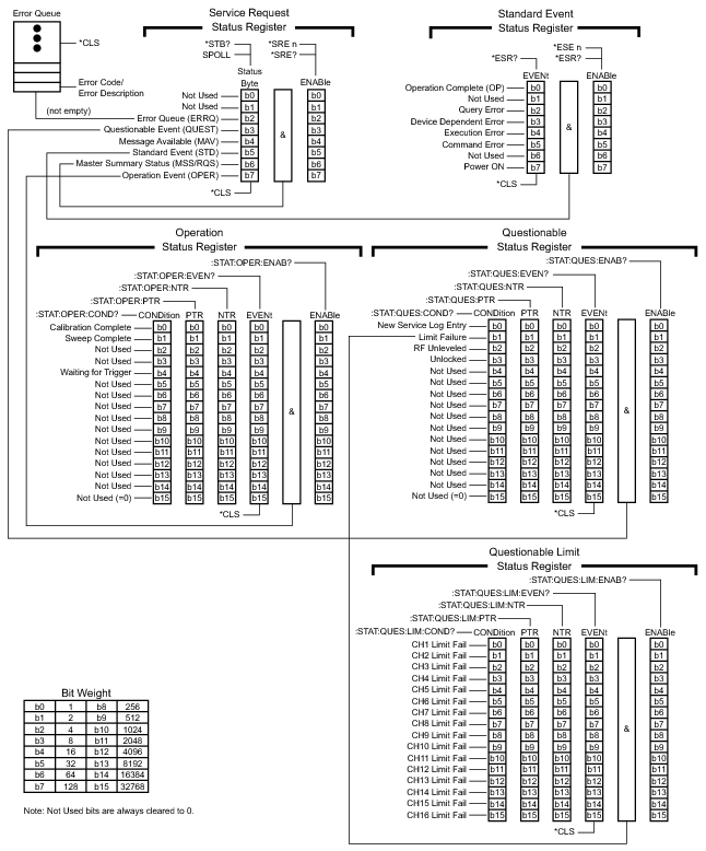
The MS4640A status system consists of the following SCPI-defined status-reporting structures:
• The Instrument Summary Status Byte Group
• The Standard Event Status Group
• The Operation Status Group
• The Questionable Status Group
The following paragraphs describe the registers that make up a status group and explain the status information that each status group provides.
Note
Parallel Polling is not supported in the MS4640A VNA.
Status Group Registers
In general, a status group consists of a condition register, a transition filter, an event register, and an enable register. Each component is briefly described in the following paragraphs.
Condition Register
The condition register is continuously updated to reflect the current status of the MS4640A. There is no latching or buffering for this register, it is updated in real time. Reading the contents of a condition register does not change its contents.
Transition Filter
The transition filter is a special register that specifies which types of bit state changes in the condition register will set corresponding bits in the event register.
• Negative transition filters (NTR) are used to detect condition changes from True (1) to False (0).
• Positive transition filters (PTR) are used to detect condition changes from False (0) to True (1).
• Setting both positive and negative filters True allows an event to be reported anytime the condition changes.
• Transition filters are read-write.
• Transition filters are unaffected by queries or *CLS (clear status) and *RST commands.
Event Register
The event register latches transition events from the condition register as specified by the transition filter. Bits in the event register are latched, and once set they remain set until cleared by a query or a *CLS command Event registers are read only.
Enable Register
The enable register specifies the bits in the event register that can produce a summary bit. The MS4640A logically ANDs corresponding bits in the event and enable registers, and ORs all the resulting bits to obtain a summary bit. Summary bits are recorded in the Summary Status Byte. Enable registers are read-write. Querying an enable register does not affect it.
Status Group Reporting
The state of certain MS4640A hardware and operational events and conditions can be determined by programming the status system. Three lower status groups provide status information to the Summary Status Byte group. The Summary Status Byte group is used to determine the general nature of an event or condition and the other status groups are used to determine the specific nature of the event or condition. The following paragraphs explain the information that is provided by each status group. Programming commands for the status system, including examples of command usage, can be found in SCPI Commands.
Summary Status Byte Group
The Summary Status Byte group, consisting of the Summary Status Byte Enable register and the Summary Status Byte, is used to determine the general nature of a MS4640A event or condition. The bits in the Summary Status Byte provide the following:
Status Byte Group
Bit #
Bit Name
Description
0,1
Not Used
These bits are always set to 0.
2
Error Queue (ERRQ)
Set to indicate the Error Queue contains data. The Error Query command can then be used to read the error message(s) from the queue.
3
Questionable Event (QUEST)
Set to indicate the Questionable Status summary bit has been set. The Questionable Status Event register can then be read to determine the specific condition that caused the bit to be set.
4
Message Available (MAV)
Set to indicate that the MS4640A has data ready in its output queue.
5
Standard Event (STD)
Set to indicate that the Standard Event Status summary bit has been set. The Standard Event Status register can then be read to determine the specific event that caused the bit to be set.
6
Master Summary Status (MSS/RQS)
Set to indicate that the MS4640A has at least one reason to require service. This bit is also called the Master Summary Status Bit (MSS). The individual bits in the Status Byte are ANDed with their corresponding Service Request Enable Register bits, then each bit value is ORed and input to this bit.
7
Operation Event (OPER)
Set to indicate that the Operation Status summary bit has been set. The Operation Status Event register can then be read to determine the specific condition that caused the bit to be set.
Standard Event Status Group
The Standard Event Status group, consisting of the Standard Event Status register (an Event register) and the Standard Event Status Enable register, is used to determine the specific event that set bit 5 of the Summary Status Byte. The bits in the Standard Event Status register provide the following:
Standard Event Status Group
Bit #
Bit Name
Description
0
Operation Complete (OP)
Set to indicate that all pending MS4640A operations were completed following execution of the “*OPC” command.
For more information, see the descriptions of the *OPC, *OPC?, and *WAI commands in IEEE Commands.
1
Not Used
The bit is always set to 0.
2
Query Error
Set to indicate that a query error has occurred.
3
Device Dependent Error
Set to indicate that a device-dependent error has occurred.
4
Execution Error
Set to indicate that an execution error has occurred.
5
Command Error
Set to indicate that a command error (usually a syntax error) has occurred.
6
Not Used
This bit should be set to 0 (zero).
7
Power ON
Set to indicate that the MS4640A is powered ON and in operation.
Operation Status Group
The Operation Status group, consisting of the Operation Condition register, the Operation Positive Transition register, the Operation Negative Transition register, the Operation Event register, and the Operation Event Enable register, is used to determine the specific condition that set bit 7 in the Summary Status Byte. The bits in the Operation Event register provide the following:
Operation Status Group
Bit #
Bit Name
Description
0
Calibration Complete
Set to indicate that a calibration is complete.
1
Sweep Complete
Set to indicate that a sweep is complete.
Note that the Sweep Complete Bit will not be set unless the sweep was started by an appropriate trigger commands.
For examples of use, see the “TRS” command in the Lightning 37xxxX Command chapter in the Programming Manual Supplement. Also see :TRIGger[:SEQuence] Subsystem in SCPI Commands.
2-3
Not Used
These bits should be set to 0 (zero).
4
Waiting for Trigger
Set to indicate that the MS4640A is in an armed “wait for trigger” state.
6-15
Not Used
These bits should be set to 0 (zero).
Questionable Status Register
The Questionable Status Register consists of the Questionable Condition register, the Questionable Positive Transition register, the Questionable Negative Transition register, the Questionable Event register, and the Questionable Event Enable register.
The Questionable Status Register is used to determine the specific condition that set bit 3 in the Summary Status Byte. The bits in the Questionable Event register provide the following:
Questionable Status Register
Bit #
Bit Name
Description
0
New Service Log Entry
Set to indicate that a new entry has been made to the Windows service log.
1
Limit Failure
Set to indicate that trace data is outside a limit line boundary.
2
RF Unleveled
Set to indicate that an RF unleveled condition exists.
3
Unlocked
Set to indicate that an internal PLL unlocked condition exists.
4-15
Not Used
These bits should be set to 0 (zero).
Questionable Limits Status Register
The Questionable Limits Status Register (QLSR) consists of the Questionable Limits Condition register, the Questionable Limits Event register, the Positive and Negative Transition Filters, and the Questionable Limits Event Enable register.
The QLSR is used to determine the channels that continuous limits testing failures and set Bit B1 of the Questionable Status Register. The bits in the QLSR provide the information described in the table below.