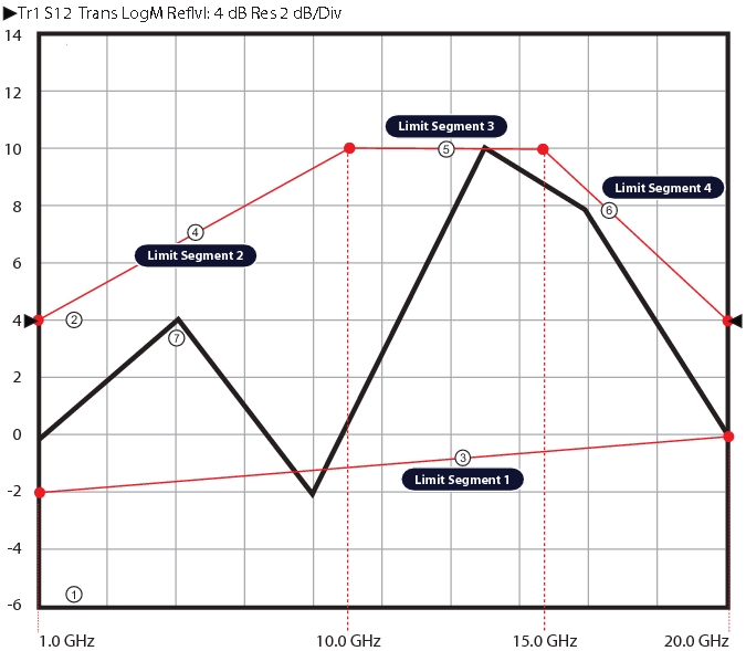
3. Limit Segment 1 – A lower limit line from 1 GHz at –2 dB to 20 GHz at 0 dB.
4. Limit Segment 2 – An upper limit line from 1 GHz at 4 dB to 10 GHz at 10 dB.
5. Limit Segment 3 – An upper limit line from 10 GHz at 10 dB to 15 GHz at 10 dB.
6. Limit Segment 4 – An upper limit line from 15 GHz at 10 dB to 20 GHz at 0 dB.
7. Typical signal trace for this DUT.
Required Equipment
• VectorStar MS4644A VNA, K Connectors, 10 MHz to 40 GHz
• Anritsu 36585K-2MF Precision Automatic Calibrator (AutoCal) Module Calibration Kit, K (male) to K (female)
Prerequisites
• The VNA has warmed up for at least 90 minutes.
• The AutoCal Module characterization file has been installed on the VNA.
DUT Requirements
The DUT measurements require the following parameters:
• S-Parameter Required: S12
• Frequency Range: 1 GHz to 20 GHz
• Segment 1: Lower Limit, -2 dB at 1 GHz to 0 dB at 20 GHz
• Segment 2: First Upper Limit, 4 dB at 1 GHz to 10 dB at 10 GHz
• Segment 3: Second Upper Limit, 10 dB at 10 GHz to 10 dB at 15 GHz
• Segment 4: Third Upper Limit, 10 dB at 15 GHz to 4 dB at 20 GHz
Channel and Trace Display Requirements
The following VNA setup parameters are required:
• Channels: 1
• Traces: 1
• Trace Display Type: Log Magnitude
• Trace Scale Resolution: 2 dB/Division
• Trace Scale Reference Value: 4 dB
• Trace Scale Reference Position: 5 (Positions the reference value above at the fifth gridline from the display counting from the display bottom.
VNA General Setup and Configuration
Throughout the script examples, long form commands are used for clarity. The command explanation follows the command. In this section, the VNA is cleared and per-instrument settings established. Optional commands or queries are noted and are presented for clarity.
:SYSTem:ERRor:CLEar
Clears the system error queue.
:SYSTem:POINt:MAXimum 25000
Set number of measurement points to 25,000 points. The instrument will reboot if the instrument was in 100,000 point mode. If already in 25,000 point mode, no instrument change and no reboot.
:DISPlay:COLor:RESet
Resets all colors to normal factory default value. This returns the channel, channel background, trace, limit line, and graticule colors to their default values.
:DISPlay:COUNt 1
Sets one (1) channel.
• When in 25,000 point mode, this can be set to 1 (one), 2, 3, 4, 6, 8, 9, 10, 12, or 16 channels.
• If the channel display is set to a non-listed number (5, 7, 11, 13, 14, 15), the instrument is set to the next higher channel number.
:CALCulate1:PARameter:COUNt 1
The command sets the number of traces as 1 on Channel 1.
:DISPlay:SPLit R1C1
Sets the channel display layout in a Row-by-Column format where channel window display is set to one channel on one row and one column. This is the same as maxmizing a multi-channel display.
:DISPlay:WINDow1:ACTivate 1
The command sets the active channel to the indicated channel number.
:DISPlay:SIZe MAXimum
Sets the maximum size of the graphic display. Not really needed here for a one channel display, but shown for a multi-channel and/or multi-trace display.
:CALCulate1:PARameter1:DEFine S12
The command sets the measurement parameter as S12 for Trace 1.
:CALCulate1:PARameter1:FORMat MLOGarithmic
The command selects the display format as Log Magnitude (MLOGarithmic) for Trace 1 on Channel 1.
Frequency and Sweep Settings
In this section, the required frequency and sweep settings are established.
:SENSe1:FREQuency:STARt 1.0E9
Sets start frequency to 1 GHz.
:SENSe1:FREQuency:STOP 20.0E9
Sets the stop frequency to 20 GHz.
:SENSe1:FREQuency:SPAN?
Optional query. Span is automatically calculated as Stop Frequency minus Start Frequency. The query returns the resulting span in Hertz.
19.0E9
Frequency span is 19 GHz.
:SENSe1:FREQuency:CENTer?
Optional query. Center frequency is automatically calculated using Stop Frequency and Start Frequency as: Fc = ((Fstop - Fstart)/2) + Fstart
10.5E9
Center frequency is 10.5 GHz
:SENSe1:SWEep:TYPe LINear
The command sets the sweep for Channel 1 as Frequency-Based Linear.
:SENSe1:SWEep:POINt 401
Sets the number of measurement points for Channel 1 to 401 points.
• The minimum number of points is 2.
• The maximum number of points is limited to the total point instrument mode as 25,000 or 100,000.
Limit Lines Setup
There are several ways to programmatically add limit lines to a trace display. The technique below uses the :CALCulate{1-16}:SELected:LIMit command subsystem in the following general procedure:
1. Create an empty limit line segment by using the :ADD command to create a blank limit.
• Note that each :ADD command must be followed by the :TYPE and :X1, :X2,:Y1, and :Y2 commands.
• The first :ADD command creates a limit line that uses the entire frequency range of the instrument.
• If the :TYPE and :X1, :X2,:Y1, and :Y2 values are not changed, no further limit line segments can be added.
2. Use the :TYPE command to define the segment as a lower or upper limit.
3. Use the :X1 and :X2 commands to configure the horizontal X-Axis start and stop points for each limit segment. In this example, the start and stop values are frequency in GHz.
4. Use the :Y1 and :Y2 commands to configure the vertical Y-Axis start and stop points for each limit segment. In this example, the start and stop values are in dB.
5. The :TYPE and :X1, :X2,:Y1, and :Y2 commands can be issued in any sequence for the segment being defined.
Clear Previous Limit Lines
Best practices recommend clearing all previous segments.
:CALCulate1:SELected:LIMit:SEGMent:CLEar
The command clears all the limit segment definitions on the active trace of the indicated channel.
Create and Configure Limit Line Segment 1
In this section, the first limit line is added, and then configured as to limit line type, start and stop frequencies, and start and stop Y-axis parameters.
:CALCulate1:SELected:LIMit:SEGMent:ADD
On Channel 1, the command adds a limit line segment. This limit line segment will be identified as Segment 1 and set as the lower limit line across the entire frequency range of interest.
:CALCulate1:SELected:LIMit:SEGMent1:TYPe LOWer
Sets the Channel 1 Segment 1 limit line type as a lower limit line.
:CALCulate1:SELected:LIMit:SEGMent1:X1 1.0E9
Sets the Channel 1 Segment 1 lower limit line start frequency value at 1 GHz.
:CALCulate1:SELected:LIMit:SEGMent1:X2 20.0E9
Sets the Channel 1 Segment 1 lower limit line stop frequency value at 20 GHz.
:CALCulate1:SELected:LIMit:SEGMent1:Y1 -2.0
Sets the Channel 1 Segment 1 lower limit start Y1 value at –2.0 dB.
:CALCulate1:SELected:LIMit:SEGMent1:Y2 0.0
Sets the Channel 1 Segment 1 lower limit stop Y2 value at 0.0 dB.
Create and Configure Limit Line Segment 2
In this section, the second limit line is added, and then configured as to limit line type, start and stop frequencies, and start and stop Y-axis parameters.
:CALCulate1:SELected:LIMit:SEGMent:ADD
On Channel 1, command adds a blank limit line segment. This limit line segment will be later identified as Segment 2 and set as the first upper limit line segment.
:CALCulate1:SELected:LIMit:SEGMent2:TYPe UPPer
Sets the Channel 1 Segment 2 limit line type as an upper limit line.
:CALCulate1:SELected:LIMit:SEGMent2:X1 1.0E9
Sets the Channel 1 Segment 2 upper limit start frequency value at 1 GHz.
:CALCulate1:SELected:LIMit:SEGMent2:X2 10.0E9
Sets the Channel 1 Segment 2 upper limit line stop frequency value at 10 GHz.
:CALCulate1:SELected:LIMit:SEGMent2:Y1 4.0
Sets the Channel 1 Segment 2 upper limit start Y1 value at 4.0 dB.
:CALCulate1:SELected:LIMit:SEGMent2:Y2 10.0
Sets the Channel 1 Segment 2 upper limit stop Y2 value at 10.0 dB.
Create and Configure Limit Line Segment 3
In this section, the third limit line is added, and then configured as to limit line type, start and stop frequencies, and start and stop Y-axis parameters.
:CALCulate1:SELected:LIMit:SEGMent:ADD
On Channel 1, the command adds a blank limit line segment. This limit line segment will be later identified as Segment 3 and set as the second upper limit line segment.
:CALCulate1:SELected:LIMit:SEGMent3:TYPe UPPer
Sets the Channel 1 Segment 3 limit line type as an upper limit line.
:CALCulate1:SELected:LIMit:SEGMent3:X1 10.0E9
Sets the Channel 1 Segment 3 upper limit start frequency value at 10 GHz.
:CALCulate1:SELected:LIMit:SEGMent3:X2 15.0E9
Sets the Channel 1 Segment 3 upper limit line stop frequency value at 15 GHz.
:CALCulate1:SELected:LIMit:SEGMent3:Y1 10.0
Sets the Channel 1 Segment 3 upper limit start Y1 value at 10.0 dB.
:CALCulate1:SELected:LIMit:SEGMent3:Y2 10.0
Sets the Channel 1 Segment 3 upper limit stop Y2 value at 10.0 dB.
Create and Configure Limit Line Segment 4
In this section, the third limit line is added, and then configured as to limit line type, start and stop frequencies, and start and stop Y-axis parameters.
:CALCulate1:SELected:LIMit:SEGMent:ADD
On Channel 1, command adds a blank limit line segment. This limit line segment will be later identified as Segment 4 and set as the third and final upper limit line segment.
:CALCulate1:SELected:LIMit:SEGMent4:TYPe UPPer
Sets the Channel 1 Segment 4 limit line type as an upper limit line.
:CALCulate1:SELected:LIMit:SEGMent4:X1 15.0E9
Sets the Channel 1 Segment 4 upper limit start frequency value as 15 GHz.
:CALCulate1:SELected:LIMit:SEGMent4:X2 20.0E9
Sets the Channel 1 Segment 4 upper limit line stop frequency value at 20 GHz.
:CALCulate1:SELected:LIMit:SEGMent4:Y1 10.0
Sets the Channel 1 Segment 4 upper limit start Y1 value at 10.0 dB.
:CALCulate1:SELected:LIMit:SEGMent4:Y2 4.0
Sets the Channel 1 Segment 4 upper limit stop Y2 value at 4.0 dB.
Configure AutoCal Calibration
For this example, the Anritsu 36585K Precision Automatic Calibrator (AutoCal) Calibration Module will be used to perform the calibration. If the characterization file for the AutoCal module has not been loaded, best practices recommand using the User Interface menus to load the characterization file.
:SENSe1:CORRection:COLLect:ECAL:AUTOmatic:ORIentation:STATe OFF
Turn the AutoCal module automatic orientation detection off for Channel 1.
:SENSe1:CORRection:COLLect:ECAL:ORIentation L1R2
Set the AutoCal module orientation detection off and sets the port-to-port orientation manually for Channel 1 so that Port 1 is on the leftt and Port 2 is on the right.
:SENSe1:CORRection:COLLect:ECAL:TRUEthru OFF
The command turns off the use of the AutoCal True Thru feature, where a cable through is used during the AutoCal calibration for Channel 1. By setting this to OFF, the AutoCal module will use its Internal Thru capability to complete the calibration.