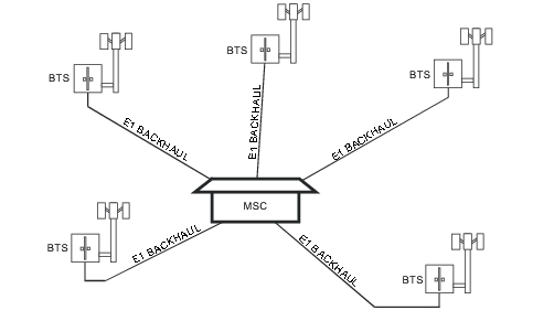
Wireless service providers use wired E1 circuits as the backhaul links to connect a Base Transceiver Station (BTS) to a Mobile Switching Center (MSC). The quality of the service that is provided over those E1 lines has a direct effect on the quality of service that is experienced by the wireless service provider customers. Call setup failures, dropped calls, data errors, and noise can often be attributed to the E1 backhaul facilities. An example of typical wireless network backhaul E1 links is shown in Figure: Typical Wireless Network Backhaul E1 Link.
Typical Wireless Network Backhaul E1 Link
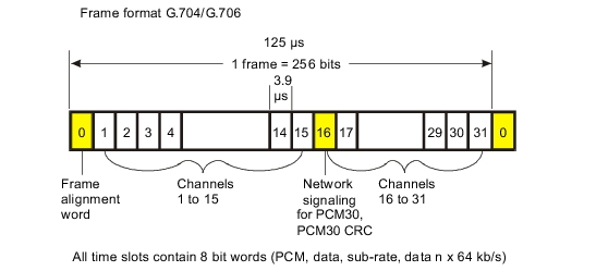
E1 is a digital signal that carries information at a rate of 2 Mb/s. The E1 signal is organized into frames, which are defined in ITU‑T recommendations G.704 and G.706. Four framing types are defined: PCM30, PCM31, PCM30CRC, and PCM31CRC. Each 2 Mb/s frame contains 256 bits (32 timeslots, each containing 8 bits) at a repetition rate of exactly 8 kHz. The first timeslot (timeslot zero, TS0) is reserved for framing, error checking, and alarm signals. In PCM31, the remaining 31 timeslots can be used for traffic (TS1 – TS31), either encoded telephone or data signals. In PCM30, timeslot 16 (TS16) is reserved for channel associated signaling (CAS). Framing types PCM30 CRC and PCM31 CRC add a CRC‑4 check to the framing format.
FAS and NFAS Words
The transmit and receive ends of the transmission path are synchronized with a frame alignment byte or signal (FAS = S10011011) that is transmitted in TS0 of every second frame (frames 0, 2, 4, 6, and so on). A “nonframe alignment signal” (NFAS) is transmitted in TS0 of the alternate frames (that is, frames 1, 3, 5, 7 and so on).
After an FAS word has been correctly received, a ‘1’ is expected in bit 2 of the NFAS word that is received in the next frame. If this occurs, and if the next frame contains a valid FAS word, then frame alignment is achieved. The receiving equipment can then correctly identify the individual 64 kb/s channels in the frame. If three frame alignment words in four are received in error, then the terminal equipment declares loss of frame synchronization and initiates resynchronization.
Transmission Frame Alignment
CRC‑4 Framing
When the PCM30 and PCM31 framing formats are used exclusively for PCM voice transmission, the frame alignment is very reliable. However, when data is transmitted on the link, the traffic can contain the FAS and NFAS bit patterns, and false framing is possible.
To improve the reliability of the standard framing formats, recommendation G.704 specifies the use of a CRC‑4 cyclic redundancy check for 2 Mb/s systems. CRC‑4 framing provides reliable protection against incorrect synchronization, and also provides a means of predicting bit error ratio (BER) performance during normal operation. The CRC‑4 remainder is calculated on complete blocks of data, and the 4‑bit remainder is transmitted to the far end, using the first bit in the FAS of each even numbered frame (C1 – C4). At the receiving end, the receiver makes the same calculation and compares its results with those in the received signal. If the two 4‑bit words differ, then the receiving equipment determines that one or more errors are present in the payload. Every bit of the block is checked so that an accurate estimate of block error rate (or errored seconds) is made while the link is in-service.
CRC‑4 Framing
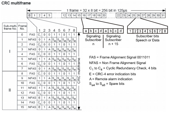
To enable the receiver to locate the four bits (C1, C2, C3, and C4) that form the remainder, an additional frame (called the CRC multiframe) is formed. A CRC multiframe alignment bit pattern (001011) is used to synchronize the receiver to this frame. The pattern is inserted in the first bit position of the NFAS in frames 1, 3, 5, 7, 9, and 11. The CRC‑4 multiframe is further divided into sub‑multiframes (SMF) I and II, both of which span eight normal PCM frames. Because each PCM frame is 125 μs long, each SMF is 1 ms long, and one thousand CRC‑4 error checks are made every second.
The first bits of frame 13 and frame 15 are called E‑bits, and are used to indicate that data blocks with bit errors were detected from the far end. When no errors are detected in the received data, both E‑bits are set to one (1). When an error is detected in SMF I, the receiving equipment sets the E‑bit in frame 13 to zero (0). The E‑bit in frame 15 indicates error status from SMF II in the same way. As a result, the local equipment can use the E‑bits to monitor the performance of both the transmit and receive paths.
Signaling
Signaling is used in networks to set up the connections between the transmitting and receiving ends of a circuit. Two methods are available to carrying signaling information in E1 frames: common channel signaling (CCS) and channel associated signaling (CAS). With CCS, the signaling data is carried in each channel. For CAS, the signaling data for all thirty channels is carried in TS16. The signaling information for each channel consists of four bits that are called ABCD bits. Historically, the state of the ABCD bits represented the On‑hook and Off‑hook states of a dial‑pulse telephone.
The 8 bits in TS16 are not sufficient to hold the signaling information for all 30 channels in a single E1 frame. Therefore, when CAS is used, a signaling multiframe structure is required in order to distribute the signaling information over 16 E1 frames. After the equipment has gained primary frame alignment, it searches in timeslot 16 for the signaling multiframe alignment signal (MFAS) (0000) in bits 1 to 4. After the MFAS signal is located, the signaling information is extracted in the 15 frames following the MFAS, with the ABCD bits (for two channels) contained in each TS16.
If CCS (common channel signaling) is used, then signaling multiframe alignment is unnecessary. Timeslot 16 is used as a 64 kb/s data channel for CCS messages, or it can be turned over to revenue‑earning traffic, yielding a total of 31 channels for the payload (PCM31).