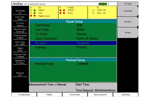
The configuration is accessed by pressing the Configuration main menu key. This menu is used to configure the Signal Setup and Payload Setup. The Signal Setup allows the user to set up the Line Code, Tx Clock, Input Connector, Rx Input, and Framing information. The Payload Setup allows the user to set up the payload type and payload channels for payload types other than 2.048 Mb.
E1 is a 2.048 Mb/s signal consisting of 32 individual timeslots. Each timeslot has individual 64 kb/s channels of data.
Line Code: HDB3 and AMI
Alternate Mark Inversion (AMI) and High Density Bipolar 3 (HDB3) are two different line coding formats used in E1 networks.
In the AMI format, a binary one is represented by a pulse, and a zero is indicated by the lack of a pulse. To eliminate any DC offset, the pulses alternate in polarity. Because the pulses are alternating in polarity, the line code is called Alternate Mark Inversion (AMI). If two consecutive pulses have the same polarity, then a Bipolar Violation (BPV) has occurred.
When no traffic is present on a channel, AMI coding can result in long strings of zeros on the circuit. This can cause the receiving equipment to have timing errors. HDB3 is a line coding format which also has no DC offset, but which replaces strings of 4 or more zeros with a specific code containing a BPV. The next HDB3 insertion uses the opposite polarity to maintain a net zero DC offset on the circuit. The HDB3 code is detected and removed by the receiving equipment.
TxClock: Internal, Recovered, External
Internal Clock: Use the internal clock oscillator (2.048 MHz ± 5ppm)
Recovered Clock: The transmit clock uses the frequency recovered from the received signal.
External Clock: The transmit clocks uses the external clock that is applied to the External Trigger In connection.
Terminate: The signal is terminated in 120 ohms or 75 ohms depending on selected Input Connector.
Monitor: The connection to the circuit is made through a monitor jack. The jack is isolated from the circuit with resistors, and the signal is typically 20 dB down from the nominal signal level. When Monitor is selected, 20 dB of flat gain is added at the receiver input.
Bridge: The input impedance of the receiver is greater than 1000 ohms. The bridged mode is used when connecting directly to an in-service E1 circuit to avoid causing a “hit” on the signal and to avoid disrupting service.
Measuring Clock and Frame Slips in E1 Mode
If an E1 SETS (Synchronous Equipment Timing Source) reference clock is available, then it can be used to measure clock slips and frame slips on the circuit under test. If two or more E1 circuits are present, then one of these can be used as a reference.
To count clock slips, connect the reference clock to the Ext Trigger In connector on the instrument. The presence of the clock is automatically detected, and when a measurement is started, the number of clock slips and frame slips are reported. When the clock frequencies are very close, the clock slip count will hover around zero. If the frequency of the circuit under test is higher than the reference frequency, then the count will grow positive. If the frequency of the circuit under test is lower than the reference frequency, then the count will grow negative. One frame slip is counted for 256 clock slips.
Framing
PCM30: 30 voice or data channels, TS16 is used for CAS, no CRC‑4 multiframe.
PCM30 CRC: 30 voice or data channels, TS16 is used for CAS, with CRC‑4 multiframe.
PCM31: 31 voice or data channels, no CRC‑4 multiframe.
PCM31 CRC: 31 voice or data channels, with CRC‑4 multiframe.
Payload Type
The Payload identifies which portion of the 2 Mb/s data stream will be accessed for testing.
2.048 Mb: The entire data stream (excluding TS0, and TS16 when CAS is active) is tested.
Nx64kb/s: Selected combinations of 64 kb channels are tested. This mode is referred to as fractional E1.
64 kb: A single 64 kb channel is tested.
16 kb: 2 consecutive bits within a selected 64 kb channel are tested.
8 kb: A single bit within a selected 64 kb channel is tested.