E1 circuit testing can be performed with either of two methods: In-service testing or Out-of-service testing. In-service testing is done during routine maintenance. This can be accomplished without removing the E1 circuit from service and without interrupting live traffic. Monitoring live traffic allows the wireless service provider technician to detect alarms, bipolar violations (BPV), and frame errors, but does not allow direct BER measurements. However, bit errors may be estimated by measuring CRC errors and E‑bit errors.
Out-of-service testing is done when the E1 is initially installed and before final acceptance from the service provider. At that time the circuit should be subjected to critical testing to guarantee the level of service per contract. Out-of-service testing may also be performed when the circuit performance is very poor. For out-of-service testing, the E1 circuit should be removed from service to allow detailed performance testing.
In-service Testing
In order to avoid disrupting service, the Bridged or Monitor receiver settings must be used when testing an E1 circuit that is in-service. The following measurements are used to check the E1 performance during regular maintenance:
• Vpp measurement
• Carrier Frequency
• Frame Sync
• CRC errors and E‑bits
• Clock and Frame Slips
• VF (audible assessment of the signal quality of the circuit)
E‑bits and CRC are very useful for in‑service testing to monitor E1 BER performance. Even when the E1 circuit is down, these tests can be useful to identify the faulty section of the circuit. If the primary errors that are detected are E‑bit errors, then the transmit path is most likely to be faulty. If the primary errors that are detected are CRC errors, then the receive path is most likely to be faulty.
Required Equipment
• The appropriate connection interfaces from the instrument to the E1 circuit under test are: 75 ohm coax, 120 ohm RJ48c and 75 ohm RJ48c. E1 cables with any of these interfaces and with the appropriate interface for their respective E1 circuit panel are sufficient for performing E1 tests.
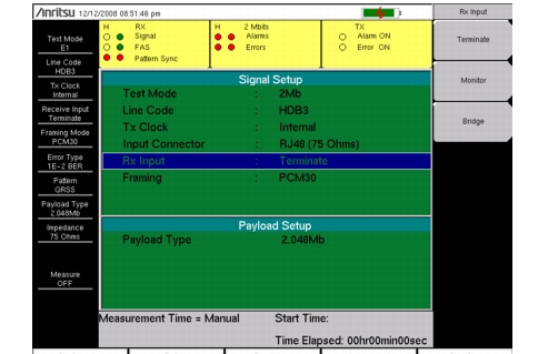
Measurement Setup Procedure
1. Press the Configuration main menu key.
2. Use the Up/Down arrow keys or the rotary knob to highlight Line Code and press the HDB3 or the AMI coding submenu key.
3. Use the Up/Down arrow keys or the rotary knob to highlight Tx Clock and select Internal, Recovered, or External.
4. Use the Up/Down arrow keys or the rotary knob to highlight Input Connector. Select from RJ48 120 ohms, RJ48 75 ohms, or BNC 75 ohms (Option 52 only).
5. Use the Up/Down arrow keys or the rotary knob to highlight Rx Input. Select from Terminate, Monitor, or Bridge. For in-service testing, select Bridge or Monitor, as appropriate for the connection.
Note
The Bridge or Monitor selection must be made before the instrument is connected to the circuit.
6. Use the Up/Down arrow keys or the rotary knob to highlight Framing. Select PCM30, PCM30CRC, PCM31, or PCM31CRC.
Note
The setup parameters are displayed in the setup summary table on the left side of the screen.
Screen captured images are provided as examples. The image and measurement details shown on your instrument may differ from the examples in this user guide.