The VF Channel Access test feature enables testing on each of the 32 channels of the E1 line. The receive channel is decoded, and the VF level and frequency are measured and displayed. The signal is also connected to a speaker, enabling the tester to make an audible assessment of the signal quality of the circuit. If the circuit is out-of-service, then a test tone can be inserted on the transmit channel for measurement at a remote location with another test set, or locally with a loopback.
Configuration
Before conducting channel tests, the E1 interface must be properly configured. From the Configuration menu, select the correct Framing Mode, Line Coding, and Clock Source. If the testing is in‑service, then the Rx Input must be configured for either Bridged or Monitor modes. The receive mode should be set up before connecting to the circuit in order to avoid creating a “hit” on the customer data. The instrument transmit pair should not be connected to the circuit. If the measurement is out‑of‑service, then the Receive Input mode should be terminated, and the instrument transmitter can be safely connected to the circuit. The current configuration of the E1 interface is displayed in the status window on the left side of the screen.
Channel Tests
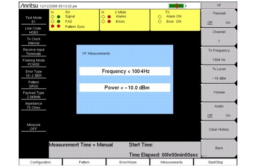
After the unit is correctly configured, select the VF Channel Access menu to perform tests at the channel level. Press the Select Channel submenu key to select specific channels. Either enter a specific channel number from the keypad or scroll through the channels with the Up/Down arrow keys. The received VF level and frequency on the selected channel are displayed, and the decoded signal is connected to a speaker for audio monitoring. When a test tone is present on the channel, the power and frequency report indicate whether the channel is healthy. If speech is present on the channel, then the channel performance can be judged from the audio quality. An overview of channel utilization can be formed by quickly scrolling through the channels.
If the circuit is out‑of‑service, then the user can connect to the transmit pair and insert a test tone on the selected channel (note that transmit and receive must be on the same channel). Two menus enable selection of transmit level and frequency. The frequency can be entered from the keypad, or scrolled to common test frequencies (404 Hz, 1004 Hz, 1804 Hz, and 2713 Hz) with the Up/Down arrow keys or the rotary knob. To check the performance of channel level equipment, the test tone can be measured at a remote location with another VF channel test set.