1. Using the test port extension cable, connect the signal source to the RF In test port.
2. Press the Freq main menu key, press the Center Freq submenu key, and enter the center frequency.
3. Press the Span main menu key. Set the span wide enough to include the primary channel bandwidth and upper and lower channel bandwidths.
4. Press the Amplitude main menu key, then press the Reference Level submenu key and set the reference level to –20 dBm.
5. Press the Auto Atten submenu key set the attenuation to On.
6. Press the BW main menu key, then use the RBW and VBW submenu keys to set the resolution bandwidth to 3 kHz and the video bandwidth to 300 Hz.
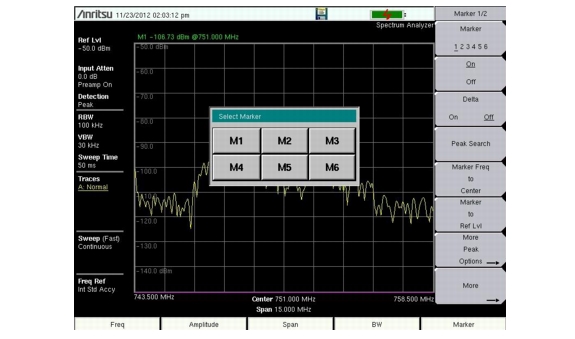
7. Press the Marker main menu key and press the Marker 123456 submenu key to select Marker 1. The underlined number indicates the active marker.
Select Active Marker (Touch Screen Models)
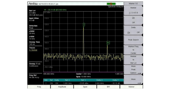
8. Press the On/Off submenu key to activate the marker. Use the arrow keys, the keypad and the knob to move the marker over one of the spurs. To use the corresponding delta marker, press the Delta submenu key so that On is underlined. Use the arrow keys or rotary knob to move the delta marker to the desired frequency and press Enter.
9. Compare the value of the marker to the specified allowable level of out‑of‑band spurious emissions for the corresponding channel transmit frequency.
10. Repeat Step 8 and Step 9 for the remaining spurs. Use either Marker 1 again, or choose another marker. Figure: Out‑of‑Band Spurious Emission Measurement shows a simulated out‑of‑band spurious signal 3 MHz from the carrier using a delta marker.