 |
|
 |
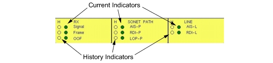 | ||
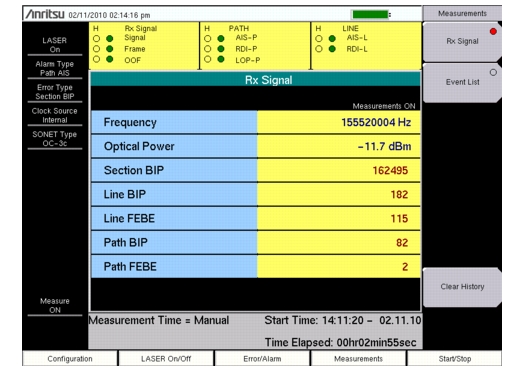
RX Signal: A red dot indicates a Loss of Signal (LOS). A LOS occurs when the synchronous signal (OC-3c) level drops below the threshold at which a BER of 1 in 1,000 or 103 is predicted. The LOS state clears when two consecutive framing patterns are received and no new LOS conditions are detected. Frame: Loss of Frame (LOF) occurs when the OOF state exists for 3 milliseconds. The LOF state clears when an in-frame condition exists continuously for a specified time in milliseconds. OOF: Out of Frame (OOF) is declared when invalid framing patterns (A1 and A2 bytes) are received for four or five consecutive SONET frames. The OOF is cleared when at least two consecutive SONET frames are received with valid framing patterns. | SONET PATH AIS-P: Path AIS (AIS-P) signal is generated when an OC Path LOS and/or LOF and/or LOP is detected. An LTE generates AIS-P by filling the entire OC SPE with a all-1’s, including H1, H2, and H3 bytes (after scrambling). The signal is sent downstream to the OC LTE. An RDI signal is sent upstream if the AIS is only for LOS or for LOF (not for LOP). RDI-P: The Path RDI (RDI-P) signal indicates to an OC PTE that a downstream defect has occurred along the OC Path. The RDI-P is cleared when a zero is in bits 5 & 6 of the G1 byte for five to ten consecutive frames. It is also cleared when it has detected an AIS-P defect on the affected path. LOP-P: Path LOP (LOP-P) state occurs when N consecutive invalid pointers are received or “N” consecutive New Data Flags (NDF) are received (other than in a concatenation indicator), where N = 8, 9, or 10. LOP state is cleared when three equal valid pointers or three consecutive AIS indications are received. | Line AIS-L: Line AIS (AIS-L) is generated by Section Terminating Equipment (STE) upon the detection of a LOS or LOF defect on an equipment failure. AIS-L maintains operation of the downstream regenerators, and therefore prevents generation of unnecessary alarms. At the same time, data and orderwire communication is retained between the regenerators and the downstream LTE. RDI-L: Line RDI (RDI-L) is a signal returned to the transmitting LTE upon detecting a LOS, LOF, or AIS-L defect. |