SONET (Synchronous Optical Network) is a standard for optical telecommunications. The International Telecommunication Union (ITU) established an international standard based on the SONET specifications known as the Synchronous Digital Hierarchy (SDH).
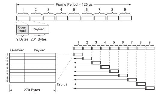
SDH multiplexing combines low-speed digital signals such as 2, 34, and 140 Mbit/s signals with required overhead to form a frame called Synchronous Transport Module at level one, STM-1. The STM-1 frame is created by 9 segments of 270 bytes each. The first 9 bytes of each segment, called the Section Overhead (SOH), carries overhead information. The remaining 261 bytes, called the virtual container at level four (VC-4), carries payload data. When visualized as a block, the STM-1 frame appears as 9 rows by 270 columns of bytes. The STM-1 frame is first transmitted row 1, with the most significant bit (MSB) of each byte transmitted first. See Figure: STM-1 Frame for an illustration of an STM-1 frame.
STM-1 Frame
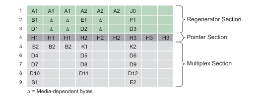
STM-1 dedicates three rows for the Regenerator Section Overhead (RSOH), Row #4 for Pointers, and five rows for the Multiplex Section Overhead (MSOH). The Virtual Container-4 contains one column for the VC-4 path overhead (VC-4 POH), leaving the remaining 260 columns for payload data (149.76 Mbit/s).
STM-1 Overhead Structure
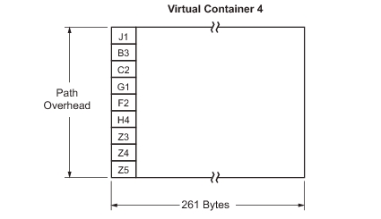
Path Overhead and Virtual Container 4 Payload Structure
SDH operates at the basic rate of 8 kHz, or 125 microseconds per frame, so the frame rate is 8,000 frames per second. The frame capacity of a signal is the number of bits contained within a single frame.
Frame Capacity = 270 bytes/row x 9 rows/frame x 8 bits/byte = 19,440 bits/frame
The bit rate of the STM-1 signal is calculated as follows:
Bit Rate = 8,000 frames/second x 19,440 bits/frame = 155.52 Mbit/s
Overheads
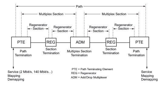
STM-1 provides substantial overhead information, allowing simpler multiplexing and greatly expanded Operations, Administration, Maintenance, and Provisioning (OAM&P) capabilities. The overhead information has several layers, which are shown in Figure: STM-1 Overhead Layers. Path Layer overhead is carried from end-to-end between path terminating equipment (PTE). Multiplex Section Layer is for the STM-1 signals between the multiplex section termination equipment: PTE and ADM. The Regenerator Section Layer is used for communications between adjacent network elements, such as PTEs, ADM, and regenerators.
Enough information is contained in the overhead to allow the network to operate and allow OAM&P communications between an intelligent network controller and the individual nodes. The following sections detail the different SDH overhead information:
• Regenerator Section Overhead (RSOH)
• Multiplexer Section Overhead (MSOH)
• Path Overhead (POH)
STM-1 Overhead Layers
Regenerator Section Overhead (RSOH)
RSOH contains nine bytes of the transport overhead accessed, generated, and processed by section-terminating equipment. This overhead supports functions including:
• Performance monitoring
• Local orderwire
• Data communication channels to carry information for OAM&P
• Framing
This might be two regenerators, line terminating equipment, and a regenerator, or two line terminating equipment. The Section Overhead is found in the first three rows of Columns 1 through 9. Refer to Figure: STM-1 Overhead Structure.
Multiplex Section Overhead (MSOH)
MSOH contains 17 bytes of overhead accessed, generated, and processed by Path Terminating Equipment (PTE) and Add/Drop Multiplexer (ADM). This overhead supports functions including:
VC-4 Path Overhead contains nine evenly distributed Path Overhead bytes each 125 microseconds starting at the first byte of the VC-4. The POH provides for communication between the point of creation and point of disassembly at the PTE. This overhead supports functions including:
• Performance monitoring of VC-4
• Signal label (the content of the VC-4, including status of mapped payloads)
BIP calculations are performed over each layer of the SDH overhead, such that each bit in the BIP byte will indicate the parity of all respective bits in the previous frame. For example, if the number of bits equaling one in the first bit position of every byte is odd, then the first bit position of the BIP byte will be 1. This is repeated for all eight bits of each byte to determine the value of the BIP byte.
Bytes in Transmitted Signal = 0110 0100
1000 0110
………….
1010 0110
BIP Calculation = 0100 0100
Each layer calculates the BIP for all information in its domain. For example, the entire SDH signal is formed when the RSTE sees it, so the Regenerator Section BIP is calculated over the entire signal, including all RSOH, MSOH, VC-4 POH, and payload of the previous STM-N frame. The result is then placed in the B1 byte for STM-1. Multiplex Section BIPs are calculated over the previous STM-1 frame, minus the RSOH, and placed in the B2 bytes. Path BIPs are calculated over the previous frame, minus RSOH and MSOH, and are found in the B3 byte of every STM-1.
STM-1 Measurements
Signal quality measurements, using the Anritsu handheld instrument, consist of reporting the total number of BIPs within the RSOH, MSOH, and POH.
RSOH BIP
Section error monitoring. Contains BIP-8 of all bits in the previous frame using even parity, after scrambling and placed in the B1 byte of the next frame before scrambling.
MS BIP
Line error monitoring. Contains BIP-24 calculated over the previous frame excluding the SOH before scrambling, and placed in the B2 byte of the next frame before scrambling.
MS-REI
The M1 byte of an STM-1 or the first STM-1 of an STM-N is used for a MS layer remote error indication. Bits 2 to 8 of the M1 byte are used to carry the error count of the interleaved bit blocks that the MS BIP-24xN has detected to be in error at the far end of the section. This value is truncated at 255 for STM-N >4.
HP BIP-8
The number of BIP-8 errors detected by the peer PTE and reported to the sender in the B3 byte.
HP REI
The number of BIP-8 errors detected by the peer PTE and reported to the sender in bits 1 to 4 of the G1 byte.
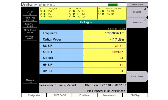
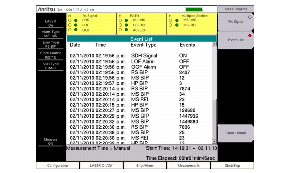
These values along with frequency and optical power are listed in a table on the measurement Rx Signal display. Accumulated and real-time numerical values can be viewed in the measurement Event List display. If Event List is selected, the display will list up to 1000 errored seconds. Refer to Figure: Rx Signal Summary Display and Figure: Event List Display.
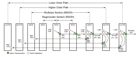
In the yellow rectangle viewing area above the Rx Signal/Event List display, historical (H) and current pass/fail conditions for parameters relating to Receive (Rx) Signal, Path, and Multiplex Section are reported. For Rx Signal, the parameters are LOS, LOF, and OOF. For Path, the parameters are AU-AIS (Alarm Indication Signal), HP-RDI (Remote Defect Indicator), and AU-LOP (Loss of Pointer). For the Multiplex Section, the parameters are MS-AIS and MS-RDI. SDH defects, errors, and alarms are shown in Figure: SDH Network Alarm Detection and Transmission.
.
Rx Signal Summary Display
Event List Display
SDH Network Alarm Detection and Transmission
RX Signal
LOS: A red dot indicates a loss of signal. A LOS occurs when the synchronous signal (STM-1) level drops below the threshold at which a BER of 1 in 103 is predicted. The LOS state clears when two consecutive framing patterns are received and no new LOS conditions detected.
LOF: Loss of frame occurs when the OOF state exists for a specified time in microseconds. The LOF state clears when an in-frame condition exists continuously for a specified time in microseconds.
OOF: Out-of-Frame (OOF) is declared when invalid framing patterns (A1 and A2 bytes) are received for four or five consecutive SDH frames. The OOF is cleared when at least two consecutive SDH frames are received with valid framing patterns.
PATH
AU-AIS: (Path AIS) An AU-AIS, an all 1’s pattern, is generated when a Multiplex Section Terminating Equipment (MSTE) LOS or LOF is detected. The signal is sent forward to the PTE. An MS-RDI signal is sent back if the AU-AIS is for LOS or LOF only (not for LOP).
HP-RDI: (Path RDI) This signal indicates to a PTE that a downstream LOS, LOF, or AIS defect has occurred along the Path.
AU-LOP: (Path LOP) LOP state occurs when N consecutive invalid pointers are received or “N” consecutive New Data Flags (NDF) are received (other than in a concatenation indicator), where N = 8, 9, or 10. LOP state is cleared when three equal valid pointers or three consecutive AIS indications are received.
Multiplex Section
MS-AIS: MS-AIS, an all 1’s pattern, is generated by the Regenerator Section Terminating Equipment (RSTE) upon the detection of a LOS or LOF defect. MS-AIS maintains operation of the forward regenerators, and therefore prevents generation of unnecessary alarms. At the same time, data and orderwire communication is retained between the regenerators and the forward MSTE.
MS-RDI: ( RDI) A signal returned to the transmitting equipment upon detecting a LOS, LOF, or MS-AIS defect.