Display the configuration screen by pressing the Configuration main menu key. This function is used to configure the Signal Setup and Payload Setup.
Signal Setup allows the user to set up the Test Mode, Line Code, Tx Clock, Tx LBO, Rx Input, and Framing information.
Payload Setup allows the user to configure the Payload Type, Payload DS1 Channel, Payload DS0 Channel, and Other Channels that are to be tested.
Submenu keys for the T1 Configuration Menu are described in section Configuration Menu.
Signal Setup
Test Mode: AUTO
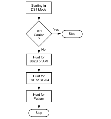
When AUTO is selected, the instrument first compares the connected signal with the current status of frame sync and pattern sync. If both are synchronized with the connected signal, then no further action is taken. If the signals are not already synchronized, then the AUTO function searches for a Line Code to match the connected signal, then searches for the framing mode of the connected signal, then searches for a matching signal pattern.
AUTO Configuration
Line Code: B8ZS or AMI
B8ZS and Alternate Mark Inversion (AMI) are two different line coding formats that are used in T1 networks.
In the AMI format, a binary one is represented by a pulse, and a zero is indicated by the lack of a pulse. To eliminate any DC offset, the binary one pulses are bipolar (they alternate in polarity). Because the pulses are alternating in polarity, the line code is called Alternate Mark Inversion (AMI). If two consecutive pulses have the same polarity, then a Bipolar Violation (BPV) has occurred.
When no traffic is present on a channel, AMI coding can result in long strings of zeros on the circuit. These zeros can cause the receiving equipment to have timing errors. The method used in T1 systems to maintain the density of ones (as opposed to zeros) in the data stream is known as binary 8‑zero substitution, or B8ZS. For the B8ZS scheme, any time that eight consecutive zeros are detected in the data stream, the transmitter substitutes a fixed pattern of ones, zeros, and BPVs in place of those 8 zeros. The BPV is used to distinguish between a real data sequence of ones and zeros versus the fixed B8ZS pattern. Because the B8ZS fixed pattern is a known pattern, the terminating receivers can recognize the pattern and substitute the original string of 8 zeros in place of the fixed pattern.
TxClock: Internal, External, Recovered
Internal Clock: The internal clock uses an internal oscillator: 1.544 Mb/s ± 5 ppm
Recovered Clock: The transmit clock uses the frequency recovered from the received signal.
External Clock: An external clock can be applied to the External Frequency Reference Input.
Tx LBO (Transmit Line Build Out): 0 dB, – 7.5 dB, or – 15 dB
Possible values for LBO are 0 dB, – 7.5 dB, or – 15 dB. When performing a test toward the far end of a circuit at a Digital System Cross‑Connect (DSX), this will usually be 0 dB. The other values might be used when close to the equipment under test.
Rx Input: Terminate, Monitor, or Bridge
Terminate: Select Terminate for out‑of‑service testing. The signal is terminated with 100 ohms.
Monitor: The connection to the circuit is made through a monitor jack. The jack is isolated from the circuit with resistors, and the signal is typically 20 dB down from the nominal signal level. When Monitor is selected, 20 dB of flat gain is added at the receiver input.
Bridge: The input impedance of the receiver is greater than 1000 ohms. The bridged mode is used when connecting directly to an in‑service T1, 1.544 MHz circuit in order to avoid causing a “hit” on the signal and to avoid disrupting service.
Framing: ESF or SF‑D4
ESF: Extended Super Frame, in which 24 frames are grouped together as an Extended Super Frame (ESF).
SF‑D4: Super Frame D4, in which 12 frames are grouped together as a Super Frame (SF).
Payload Setup
Payload Type: 1.544Mb, Nx64kb, 64kb, 56kb, 16kb, or 8kb
The Payload Type identifies which portion of the T1 data stream is to be tested.
1.544 Mb: Full T1 data stream test.
Nx64kb: Selected combinations of 64 kb channels are tested. This mode is referred to as fractional T1.
64kb: A single 64 kb channel is tested.
56kb: Data stream as a result of bit robbing.
16kb: Two consecutive bits within a single 64 kb channel are tested.
8kb: A single bit within a selected 64 kb channel is tested.
Payload DS0 Channel: # (Number)
Set up the necessary channels and sub‑channels when testing payloads Nx64kb to 8kb.
Other Channels: All ones or Idle
Set the other channels (that are not being tested) as IDLE or set them to All Ones.