3GPP Signal Analyzer for Anritsu RF and Microwave Handheld Instruments : EMF (Option 444) : LTE/TD-LTE EMF Menu
  
LTE/TD-LTE EMF Menu
Key Sequence: Measurements > Over-the-Air > EMF
LTE/TD-LTE EMF Menu
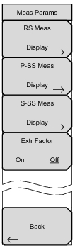
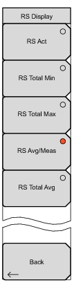
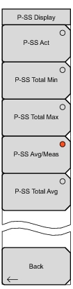
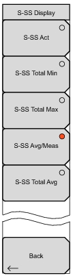
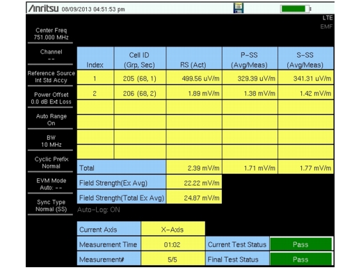
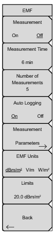
Measurement On/Off: Starts the EMF Measurement and removes access to all other menu buttons. The measurement turns On only if the Center Frequency is set within the valid range and the Anritsu Isotropic Antenna is connected.
Note that the Measurement Time and other related parameters must be set before starting the measurement. This button is useful for stopping or restarting measurements when settings need to be changed. When the measurement is in progress, access to other menus and key presses are blocked.
Measurement Time: Sets the measurement duration from one minute up to 30 minutes.
Number of Measurements: Sets the number of EMF measurements to complete from 1 up to 10,000.
Auto Logging On/Off: Auto Logging is On by default. This must be selected prior to starting the measurements for the results to be logged. The average values of RS, P‑SS, and S‑SS for each measurement are saved in a tab delimited text file in internal memory, along with the computed total average and total max values of RS, P‑SS, and S‑SS.
The location of the saved log file is a new folder named with the current time stamp followed by _1, and created in “/Internal Memory/EMF/”. The folder can hold 100 files. Each file holds five measurements. The 101st file and the files created thereafter are stored in a new folder with the same time stamp as the first, followed by _2 (then _3, and so on). Each file has its own time stamp.
Measurement Parameters: Opens the Meas Params Menu (LTE/TD-LTE).
EMF Units: dBm/m2, V/m, and W/m2 are the currently supported units. V/m is the default unit.
Limits: A single number can be entered. The Field Strength (Avg) value should stay below this limit (default 6 V/m) for the test to pass.
Back: Returns to the previous menu.
Meas Params Menu (LTE/TD-LTE)
Key Sequence: Measurements > Over-the-Air > EMF > Measurement Parameters
LTE/TD-LTE Meas Params Menu
 
 
RS Meas Display: Opens the RS Display Menu.
 
 
P-SS Meas Display: Opens the P-SS Display Menu.
 
S-SS Meas Display: Opens the S-SS Display Menu.
 
Extr Factor On/Off: Toggles On/Off the Extrapolation Factor. The extrapolation factor, if turned On, displays the extrapolated field strength number for the selected capture bandwidth.
 
Back: Returns to the LTE/TD-LTE EMF Menu.
RS Display Menu
Key Sequence: Measurements > Over-the-Air > EMF > Measurement Parameters > RS Meas Display
RS Display Menu
 
The displayed Reference Signal parameters below can be changed at the start or at the end of the measurement cycle. All of the parameters are always computed and stored. Once the measurement is complete, any combination of parameters can be viewed (three at a time and in any one of the desired units).
RS Act: Selects the display of Actual Value (current isotropic number).
RS Total Min: Selects the display of Total Min (the minimum value for the entire measurement period).
RS Total Max: Selects the display of Total Max (the maximum value for the entire measurement period).
RS Avg/Meas: Selects the display of Avg/Meas (running average for the current measurement interval). This is the default selection.
RS Total Avg: Selects the display of Total Avg (running average for the entire measurement period).
 
Back: Returns to the Meas Params Menu (LTE/TD-LTE).
P-SS Display Menu
Key Sequence: Measurements > Over-the-Air > EMF > Measurement Parameters > P-SS Meas Display
P-SS Display Menu
 
The displayed Primary Synchronization Signal parameters below can be changed at the start or at the end of the measurement cycle. All of the parameters are always computed and stored. Once the measurement is complete, any combination of parameters can be viewed (three at a time and in any one of the desired units).
P-SS Act: Selects the display of Actual Value (current isotropic number).
P-SS Total Min: Selects the display of Total Min (the minimum value for the entire measurement period).
P-SS Total Max: Selects the display of Total Max (the maximum value for the entire measurement period).
P-SS Avg/Meas: Selects the display of Avg/Meas (running average for the current measurement interval). This is the default selection.
P-SS Total Avg: Selects the display of Total Avg (running average for the entire measurement period).
 
Back: Returns to the Meas Params Menu (LTE/TD-LTE).
S-SS Display Menu
Key Sequence: Measurements > Over-the-Air > EMF > Measurement Parameters > S-SS Meas Display
S-SS Display Menu
 
The displayed Secondary Synchronization Signal parameters below can be changed at the start or at the end of the measurement cycle. All the parameters are always computed and stored. Once the measurement is complete, any combination of parameters can be viewed (three at a time and in any one of the desired units).
S-SS Act: Selects the display of Actual Value (current isotropic number).
S-SS Total Min: Selects the display of Total Min (the minimum value for the entire measurement period).
S-SS Total Max: Selects the display of Total Max (the maximum value for the entire measurement period).
S-SS Avg/Meas: Selects the display of Avg/Meas (running average for the current measurement interval). This is the default selection.
S-SS Total Avg: Selects the display of Total Avg (running average for the entire measurement period).
 
Back: Returns to the Meas Params Menu (LTE/TD-LTE).
Measurement Results (LTE/TD-LTE)
The measurement starts by setting the antenna’s X-axis and capturing over-the-air data. If a sync signal is found and a valid Cell ID exists, then the following parameters are detected and stored: the channel power in 1.4 MHz bandwidth, the Cell ID, RS, S-SS, and P-SS (all per Resource Element). This is repeated for Y and Z axes. If any one of the axes has a valid Cell ID, the isotropic result (for example, (RS2X + RS2Y + RS2Z)0.5) for each of the above mentioned parameters is stored. There is no axis dwell time parameter. If a sync signal is not found in a specific time, the instrument switches to the next axis.
The isotropic result computed for each parameter is displayed as the Actual result. The Total Max and Total Min are the final isotropic results computed for that parameter for the entirety of the measurement (Measurement time * Number of Measurements). The Avg/Meas is the running average of the isotropic results, and Total Avg is the final average of all the isotropic numbers for each parameter computed during the entire measurement period (measurement time * number of measurements).
The Field Strength number computed is only for 1.4 MHz bandwidth. If the extrapolation factor is turned Off, this number is the Channel Power (in 1.4 MHz). Changing the bandwidth does not change this number.
If the Extrapolation factor is turned On, the Field Strength (Emax) is computed as follows:
Emax = Ecp * Ncp
where Ecp is the RMS value of the channel power recorded in each axis and Ncp is the number of subcarriers divided by 72. The number of subcarriers can be provided by the network operator or can be calculated from the table below.
Field Strength Numbers
Channel Bandwidth (MHz)
Subcarriers
1.4
72
3
180
5
300
10
600
15
900
20
1200
The Field Strength text is updated with an Ex (Field Strength (Ex Avg)) to indicate that the Extrapolation factor has been turned On.
If a valid Cell ID is obtained even once during the entire measurement period, an entry will be made in the table. “--” indicates an invalid result. A maximum of six cell IDs can be detected. The Total row below simply sums the isotropic numbers for the selected display parameter across Cell IDs.
Pass/Fail
The limit check is done at the end of a measurement period. If the Field Strength Avg (with or without extrapolation) exceeds the set limit, the Current and the Final Test Status are marked as Fail in red. If the Field Strength number does not exceed the limit, the Current Test Status is marked as Pass in green. If all of the measurements pass, the Final Test Status is updated to Pass in green.
LTE/TD-LTE EMF Measurement Display