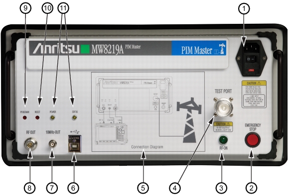
The PIM Master has the connectors that are shown in
Figure: PIM Master Connector Panel.
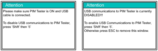
When an Anritsu handheld instrument is operating in PIM Analyzer mode, the instrument attempts to connect through the USB connection to the PIM Master. If you want to work in PIM Analyzer mode without connecting to the PIM Master, then you can press
Shift +
5 on the handheld instrument to disable USB communications. Refer to the Attention message on the left side of
Figure: USB Connection Messages.
While the connection is disabled, you can set or change frequency, amplitude, and setup parameters as desired. When you press the Measurement main menu key, the instrument again attempts to connect through the USB connection to the PIM Master. If the connection has not yet been established, an Attention message directs you to press
Shift +
5 on the handheld instrument to enable USB communications. Refer to the Attention message on the right side of
Figure: USB Connection Messages. If you want to continue working in PIM Analyzer mode without connecting to the PIM Master, then press
ESC to clear the message box.