3 This option and Option 759 are mutually exclusive.
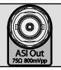
DVB ASI Out BNC Connector for BER Measurements (Option 57 and Option 79)
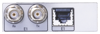
E1 Tx/Tx Connectors (Option 52, 51 or 53)
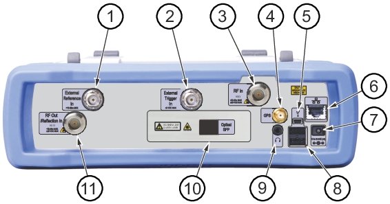
External Reference In
The External Reference In port is a 50 Ω BNC female connector that provides for input of an external frequency reference. Refer to your Technical Data Sheet for valid frequencies. To prevent damage to your instrument, do not use pliers or a wrench to tighten the BNC connector.
External Trigger In
A TTL signal that is applied to the External Trigger 50 Ω female BNC input connector causes a single sweep to occur. In the Spectrum Analyzer mode, it is used in zero span, and triggering occurs on the rising edge of the signal. After the sweep is complete, the resultant trace is displayed until the next trigger signal arrives.
Analyzer/RF In
50 Ω Type-N female connector. Maximum input is +33 dBm at ±50 VDC.
Headset Jack
The headset jack provides audio output from the built-in AM/FM/SSB demodulator for testing and troubleshooting wireless communication systems. The jack accepts a 3.5 mm 3-wire miniature phone plug such as those commonly used with cellular telephones.
USB Interface – Mini-B
The USB 2.0 Mini-B connector can be used to connect the Cell Master directly to a PC. The first time the Cell Master is connected to a PC, the normal USB device detection by the computer operating system will take place.
Note
For proper detection, the applicable Anritsu Software Tool should be installed on the PC prior to connecting the Cell Master to the USB port.
GPS Antenna Connector (Option 31)
The GPS antenna connection on the Cell Master is type SMA-female. GPS function is described in GPS (Option 31) .
To prevent damage to your instrument, do not use pliers or a plain wrench to tighten the SMA connector. Do not over-tighten the connector. The recommended torque is 8 lbf · in (0.9 N · m or 90 N · cm).
External Power
This is a 2.1 mm by 5.5 mm barrel connector, 12.5 to 15 VDC, < 4.0 A. The external power connector is used to power the unit and for battery charging. A green blinking LED near the Power button indicates that the instrument battery is being charged by the external charging unit. The indicator is a steady green when the battery is fully charged.
Warning
When using the AC-DC Adapter, always use a three-wire power cable that is connected to a three-wire power line outlet. If power is supplied without grounding the equipment in this manner, then the user is at risk of receiving a severe or fatal electric shock.
The Cell Master has two Type A USB connectors that accept USB Flash Memory devices for storing measurements, setup data, and screen images.
Rx, Tx, E1 Connectors (Options 51, 52, 53)
These options are obsolete. The ports are used in T1/T3/E1 operations described in the Backhaul Measurement Guide.
To avoid damaging your instrument, do not use pliers or a wrench to tighten the connectors.
Digital Signal Output (DVB ASI Out) BNC Connector (Options 57, 79)
The digital signal output, BNC female connector is unique to the Bit Error Rate (BER) options (Option 57 and Option 79) and is present only when one or both of these options are installed. The Digital Television Signal Analyzer options operations are described in the Digital Television Signal Analyzer Measurement Guide (refer to Measurement Guides).
To prevent damage to your instrument, do not use pliers or a wrench to tighten the BNC connector. Do not over-tighten the connector.
The DVB-ASI function produces MPEG-TS data output during a BER measurement. This output can be connected to MPEG-TS analysis equipment to monitor video errors or can be connected via appropriate ASI to USB demultiplexing and decoding accessories for channel identification and monitoring purposes.
LAN Connection (Option 413)
The RJ‑45 connector is used to connect the Cell Master to a local area network or directly to a PC with an Ethernet crossover cable. Integrated into this connector are two LEDs. The amber LED shows the presence of a 10 Mbit/s LAN connection when on, and a 100 Mbit/s LAN connection when off. The green LED flashes to show that LAN traffic is present. For more information on the LAN connection, Ethernet connection, and DHCP. Refer to Web Remote Control and LAN and DHCP.
Optical SFP (Option 759)
The optical transceiver port is used to connect the instrument to the fiber optic CPRI or OBSAI link between a Radio Frequency Module (RFM) and a Base Band Module (BBM). This SFP port is present only when Option 759 (RF over Fiber hardware) is installed. Refer to the instrument’s Technical Data Sheet for transceiver part numbers and specifications.
Note
Option 759 requires either Option 752 (CPRI LTE RF Measurements) or Option 753 (OBSAI LTE RF Measurements). The combination of Option 759 and Option 752 is functionally identical to obsolete Option 751.
RF Out (Reflection In)
RF output, 50 Ω Type‑N female connector, for reflection measurements. Maximum input is +23 dBm at ±50 VDC.