Batch measurement mode allows you the option of running multiple tests for multiple channels. Batch mode setup consists of a combination of minimal setup procedures and default measurement parameters. You are allowed to select channels from either the UHF or UHF (Brazil) channel maps. If you select IF or None, then the channel map is automatically set to UHF.
Review Table: “Common Items for All Batch Mode Measurements”, Table: “Field Strength Measurement Items for Batch Mode”, Table: “Modulation Analysis Measurement Items for Batch Mode”, and Table: “Spectrum Mask Measurement Items for Batch Mode” in the section titled “Batch Measurements” for specific measurement settings. In Batch measurement mode, Spectrum Mask, Phase Noise, and Spectrum Monitor measurements are completely preset, with no parameters that need to be set manually.
Follow this procedure to set up for Batch Measurement mode when your instrument is currently in either Easy Measurement mode or Custom Measurement mode.
|
1.
|
Press the Frequency/Level main menu key and then press the Channel Map submenu key to open the Select Channel Map list box.
|
|
2.
|
|
3.
|
|
4.
|
|
5.
|
The Batch Measurement configuration window is displayed, and the “Batch Measurement Setup Menu” is displayed. Note that no Frequency/Level main menu key and no Save Files main menu key are available.
|
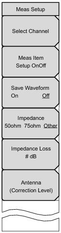 |
Select Channel
Meas Item Setup OnOff
Press this submenu key to turn each of the 4 measurements On or Off.
Save Waveform
On Off Press this submenu key to turn On or Off the ability to save measurement waveforms with the measured results.
Impedance
50 Ohm 75 Ohm Other Press this submenu key to toggle the selection to 50 ohm, 75 ohm, or Other impedance value. Selecting 75 ohm selects the 7.5 dB loss of the Anritsu 12N50‑75B adapter. For other adapters, select “Other” and enter the appropriate loss.
Impedance Loss
This submenu key is displayed only when the Impedance submenu key is set to Other. Press this submenu key to open the Impedance Loss Editor dialog box and set a dB value.
Set the impedance loss in the range of 0.0 dB to 100.0 dB (in 0.1 dB steps) when the impedance is set to Other (which is also 75 ohms). Set 1.9 dB when using the MA1621A impedance transformer as the impedance converter.
Antenna (Correction Level)
Press this submenu key to open the Select Antenna list box. Scroll through to the desired Anritsu antenna model number by using the Up/Down arrow keys or the rotary knob. Highlight the antenna model number, and then press Enter.
|
|
1.
|
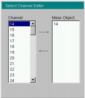
The Select Channel Editor dialog box displays the available channels (Channel column) and a list of channels that have been selected for measurement (Meas Object column). Refer to Figure: “Select Channel Menu (Batch Measurement Mode)”.
|
a.
|
Use the Up/Down arrow keys or the rotary knob to scroll through the list of channel numbers. Highlight a desired channel number and then press the Add Channel to Meas Object submenu key. Repeat this step until the desired channels are listed in the Meas Object column of the Select Channel Editor dialog box.
|
If undesired channel numbers are present in the Meas Object list, then highlight the desired channel numbers in the Channel list and press the Delete Channel from Meas Object submenu key. You can also press the Delete All Channels from Meas Object submenu key.
|
b.
|
Press Enter when you are done selecting channels.
|
|
Up to ten channels can be selected for batch measurements. The Add Channel to Meas Object submenu key does not respond after ten channels are included in the Meas Object list.
|
 |
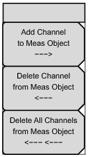 |
Add Channel to Meas Object
Press this submenu key to add the highlighted channel number (in the Channel column) to the Meas Object column list.
Delete Channel from Meas Object
Press this submenu key to delete the highlighted channel number (in the Channel column) from the list in the Meas Object column.
Delete All Channels from Meas Object
Press this submenu key to delete all of the channels from the Meas Object column.
|
|
a.
|
Use the Up/Down or Left/Right arrow keys or the rotary knob to move the green cursor to the desired measurement (displayed at the top of the measurement screen): Field Strength, CH Power, Modulation Analysis, or Spectrum Mask. You can select any or all of these four measurements.
|
|
b.
|
Press the Meas Item Setup OnOff submenu key to turn On or Off a highlighted measurement. A check mark in the box to the left of the measurement name indicates that the measurement is selected.
|
|
3.
|
To save the measurement waveforms of the test, press the Save Waveform submenu key (if necessary) so that On is underlined. Measurement waveforms are saved to file with the extension _GRP.CSV.
|
|
4.
|
Press the Impedance submenu key to toggle through the 3 settings. Select one of the three parameters: 50 ohm, 75 ohm, or Other. The current selection is underlined.
|
|
a.
|
|
b.
|
To configure the impedance loss, press the Impedance Loss submenu key and use the Up/Down arrow keys, the rotary knob, or the numeric keypad to set a value.
|
|
c.
|
The Impedance Loss Editor dialog box and the Units menu are displayed. When using the numeric keypad, enter a value and then press the dB submenu key or press Enter to set the value.
|
The impedance loss setting range is 0 dB to 100 dB in 0.1 dB increments. The Up/Down arrow keys change the impedance loss value in 1 dB steps. The rotary knob changes the impedance loss value in 0.1 dB steps.
|
5.
|
Press the Antenna (Correction Level) submenu key to open the Select Antenna list box. Scroll through to the desired Anritsu antenna model number by using the Up/Down arrow keys or the rotary knob. When the desired Anritsu antenna model number is highlighted, press Enter.
|
|
Impedance, impedance loss, and antenna model number are displayed at the bottom of the Batch Measurement configuration display.
|
|
6.
|
Press the Execute Measure main menu key to begin testing. While the batch measurement is being completed, the Execute Measure main menu key is replaced by a Stop Measure main menu key. Use the Stop Measure main menu key to abort the batch measurement.
|
As test measurements are being made, “Measuring” is displayed at the top of the measurement display. After the last selected measurement is complete, the Spectrum Monitor measurement runs automatically. The Batch test is complete after the Spectrum Monitor measurement is completed.
Field Strength, Channel Power, Modulation Analysis, and Spectrum Mask of up to 10 broadcast channels can be measured in series. Channel Power is measured during Field Strength measurements.
CW Frequency, Phase Noise, and Spurious Emissions are not measured.
Table: “Common Items for All Batch Mode Measurements”, Table: “Field Strength Measurement Items for Batch Mode”, Table: “Modulation Analysis Measurement Items for Batch Mode”, and Table: “Spectrum Mask Measurement Items for Batch Mode” provide initial values of measurement selections.
When the Channel Map selection is UHF, a screen message displays “Batch Measurement”. When the Channel Map selection is UHF (Brazil), a screen message displays “Batch Measurement (Brazil)”.
|
UHF or UHF (Brazil)
|
|
|
13 (UHF) or 14 (UHF (Brazil))
|
|
|
UHF or UHF (Brazil)
|
|
|
All the items of Field Strength, Channel Power, Modulation Analysis, and Spectrum Mask are selected.
|
|
50 times
|
|
|
50 ohm
|
|
|
0.0 dB
|
|
|
Value calculated from the table of antenna correction factors for the first antenna that is listed in the Select Antenna list box and also from the frequency
|
|
Only continuous measurement (cannot be modified)
|
|
|
Display switch between Constellation and Delay Profile
|
|
|
2/8 Fixed
|
|
|
50 dB (cannot be modified)
|
|
|
50 dB (cannot be modified)
|
|
|
Standard B (P > 2.5 W) (cannot be modified)
|
|