Land Mobile Radio Analyzer and Coverage Measurement Guide : NBFM Analyzer : Setup (1/2) Menu
 
Setup (1/2) Menu
Key Sequence: Setup
NBFM Analyzer Setup Menu 
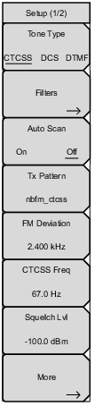
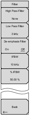
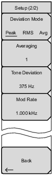
Tone Type: Sets the information displayed in the last row of the Summary table. Select Continuous Tone‑Coded Squelch System (CTCSS) for transmitters or radios using an analog squelch system. Select Digital Coded Squelch (DCS) for systems using digital squelch settings.
Select DTMF and the LMR Master will decode the Dual‑tone multi‑frequency signalling sent by the radio or transmitter.
Note: The frequency range for all 3 tone types is below the minimum spectrum display of the LMR Master in NBFM mode and also has no effect on the Tx Pattern selection.
Filters: Opens the Filters Menu.
Auto Scan: Turning Auto Scan On causes the Rx Frequency to self‑adjust to match the highest power signal detected between 10 MHz and 1.6 GHz that is above +10 dBm (10 mW) in the center of the Spectrum graph. To lock the new Rx Frequency in place, toggle Auto Scan to Off. This is available only in NBFM Analyzer measurements.
Tx Pattern: Selects the transmitter pattern to send when the Turn Sig‑Gen ON main menu key is selected. Select a pattern from the list box with the arrow keys or rotary knob and press Enter.
Patterns include CW, CTCSS, DCS, DTMF, AM, and FM.
CTCSS adds a low‑pitch audio tone (selectable between 67 Hz to 254 Hz) on the transmitted signal. When CTCSS is selected as the Tx pattern, a submenu is displayed to set the CTCSS frequency, and the Tone Deviation is set using the More submenu.
DCS superimposes a continuous stream of frequency shift keying (FSK) digital data on the transmitted signal at 134.4 bits per second. This data is referred to as a DCS word and is 23 bits. When DCS is selected as the Tx pattern, a submenu is displayed to set the DCS Type, and the Tone Deviation is set using the More submenu.
When DTMF is selected as the Tx pattern, a DTMF digit (0 to 9, A to D, *, or #) is added to the transmitted signal. The digital consist of paired tones: a row tone (697 Hz to 941 Hz) and a column tone (1209 Hz to 1633 Hz). The DTMF Tone submenu is displayed to set the DTMF Tone. Set the FM Deviation and the Tone Deviation using the More submenu.
When AM is selected as the Tx pattern, a submenu is displayed to set the percentage of Amplitude modulation. The range is 0 % to 100 %.
When FM is selected as the TX pattern, a submenu is displayed to set the cycle count of the frequency deviation. The range is 0 Hz to 100 kHz.
Setup (1/2) Menu (continued)
NBFM Analyzer Setup Menu 
FM Deviation/AM Percentage: Display of this menu is based on the selected Tx Pattern.
When AM is selected as the Tx pattern, a submenu is displayed to set the percentage of Amplitude modulation. The range is 0 % to 100 %.
When FM or DTMF is selected as the Tx pattern, a submenu is displayed to set the cycle count of the frequency deviation. The range is 0 Hz to 100 kHz.
CTCSS Freq/DCS Type/DTMF Done: Display of this menu is based on the selected Tx Pattern.
When CTCSS is selected as the Tx pattern, press the CTCSS submenu key to set the CTCSS frequency.
When DCS is selected as the Tx pattern, press the DCS Type submenu key to set the DCS Type.
When DTMF is selected as the Tx pattern, press the DTMF Tone submenu to set the DTMF character to transmit.
Note: The Tone Type submenu (top of Setup 1/2) is for the LMR Master receiver and has no effect on the Tx patterns.
Squelch Lvl: Sets the squelch power level. When the Received Power is lower than the set squelch level, all summary graph measurements except for Received Pwr will be blanked out (‑‑).
More: Opens the Setup (2/2) Menu.
Filters Menu
Key Sequence: Setup > Filters
NBFM Filters Menu
High Pass Filter: Displays a dialog box to select the cutoff frequency for the high pass filter (attenuates frequencies below the cutoff setting). Cutoff frequency options are: None (default), 300 Hz, or 3 kHz.
Low Pass Filter: Displays a dialog box to select the cutoff frequency for the low pass filter (attenuates frequencies above the cutoff setting). Cutoff frequency options are: None, 300 Hz, 3 kHz (default), or 15 kHz.
Filtering adjusts the display in both the Audio Spectrum and Audio Waveform graphs. In addition, filtering will effect the Deviation and possibly the Mod Rate values in the Summary table.
De‑emphasis Filter: This filter produces a 6 dB/octave frequency response, with a cutoff frequency of 212 Hz. FCC rules state that Part 90 analog FM systems must support the use of a 750 µs pre/de‑emphasis filter to allow older PM radios to communicate with narrowband FM radios.
IFBW: . Displays a dialog box to select the intermediate frequency bandwidth. Bandwidth options are: 5 kHz, 6.25 kHz, 10 kHz, 12.5 kHz, 30 kHz (default), or 50 kHz.
% IFBW: Scales the IFBW between 1 % to 100 %.
Back: Returns to the Setup (1/2) Menu.
Setup (2/2) Menu
Key Sequence: Setup > More
NBFM Filter Menu
Deviation Mode: Sets the deviation mode displayed in the NBFM Analyzer measurement Summary table (third row down). Rotates between Peak Deviation, RMS deviation, and Average deviation.
Averaging: Sets the refresh rate of the numerical values in the NBFM Summary window. Setting a higher number (25 maximum) will reduce measurement jitter.
Tone Deviation: Sets the cycle count of the tone deviation. The range is 0 Hz to 100 kHz.
Mod Rate: Use this menu to change the default 1 kHz modulation rate.
Back: Returns to the Setup (1/2) Menu.