This measurement is captured on an external USB flash drive. The captured data file cannot be recalled and displayed on the instrument screen.
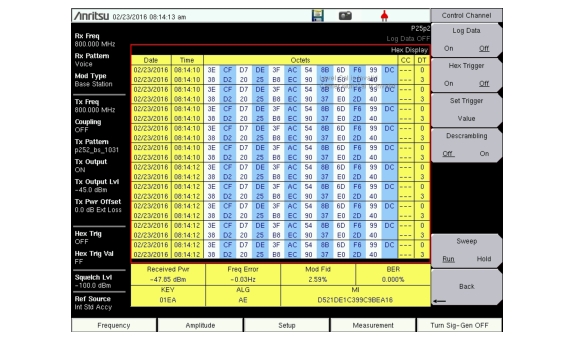
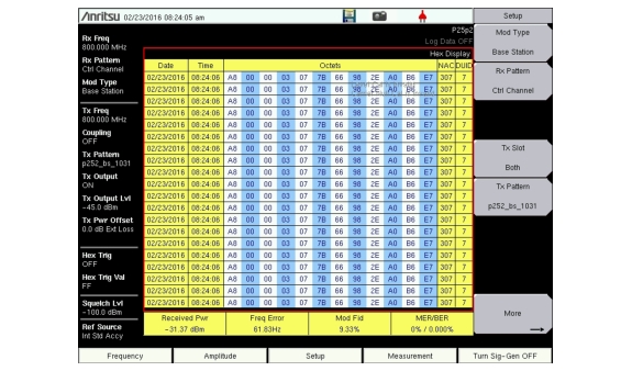
The LMR Master can log the decoded bits for control messages for either the voice channel or the control channel.
1. From the Frequency main menu, set the receiver frequency (Rx Freq).
2. From the Setup main menu, choose either Voice (downlink) or Ctrl Channel (uplink) as the Rx Pattern.
3. From the Measurement main menu press the P25p2 Control submenu key twice.
4. To log data, insert a formatted flash drive in the LMR Master and set Log Data to On.
5. The Hex Trigger menu and Hex Trigger Value menu are used to find a specific opcode in the Control Channel data.
To set the hex trigger value, press the Set Trigger Value menu. An on screen keyboard is displayed with the numbers 0 to 9 and the letters A to F. Enter the two‑character hex value to search for. After entering the value, press Enter to set the trigger value. Press Esc to cancel entry or change the current hex value.
Setting Hex Trigger to On sets the Sweep function to Hold when the hex trigger value is found in the first octet of a packet. The octet row with the found trigger value is displayed in the middle of the table (Figure: P25p2 Control Channel (Voice)). If Log Data is set to On, then all of the data on the screen are saved, and Log Data is set to Off. When Sweep is set back to Run, the unit continues to collect data and stops on the next instance of the hex trigger value. To continue to capture data on the USB flash drive, set Log Data back to On before setting Sweep to Run mode.
Figure: P25p2 Control Channel (Voice) and Figure: P25p2 Control Channel (Control) are examples of the display screen measurement in Voice and Control Channel. Valid Octet data is displayed in blue. Data displayed in red indicates a Cyclic Redundancy Check (CRC) error. P25p2 Control measurements include the following information:
CC = Color Code DT = Data Type KEY = key ID (part of encrypt sync word which identifies the encryption parameters) ALG = algorithm ID (part of encrypt sync word) MI = message ID (part of encrypt sync word)
Set Descrambling to On to decrypt the data stream based on the WACN ID, System ID, and Color Code settings.
When Log Data is set to On, the control channel information is written to a data stamped folder inside the /usr folder on the root level of the USB flash drive. The file is named: