This measurement is captured on an external USB flash drive. The captured data file can not be recalled and displayed on the instrument screen.
The LMR Master can log the decoded bits for control messages for either the voice channel or the control channel.
1. From the Frequency main menu, set the receiver frequency (Rx Freq).
2. From the Setup main menu, choose either Voice (downlink) or Ctrl Channel (uplink) as the Rx Pattern.
3. From the Measurement main menu press the NXDN Control submenu key twice.
4. To log data, insert a formatted USB flash drive in the LMR Master and set Log Data to On.
5. The Hex Trigger menu and Hex Trigger Value menu are used to find a specific opcode in the Control Channel data.
To set the hex trigger value, press the Set Trigger Value menu. An on screen keyboard is displayed with the numbers 0 to 9 and the letters A to F. Enter the two‑character hex value to search for. After entering the value, press Enter to set the trigger value. Press Esc to cancel entry or changing the current hex value.
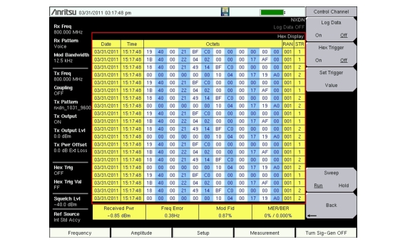
Setting Hex Trigger to On sets the Sweep function to Hold when the hex trigger value is found in the first octet of a packet. The octet row with the found trigger value is displayed in the middle of the table (Figure: NXDN Control Channel (Voice)). If Log Data is set to On, then all of the data on the screen are saved and Log Data is set to Off. When Sweep is set back to Run, the unit continues to collect data and stops on the next instance of the hex trigger value. To continue to capture data to the USB flash drive, set Log Data back to On before setting Sweep to Run mode.
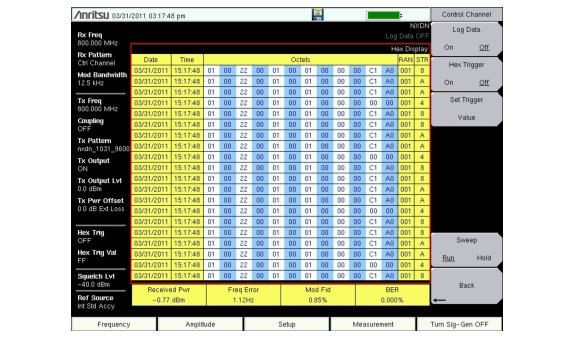
Figure: NXDN Control Channel (Voice) and Figure: NXDN Control Channel (Control) are examples of the display screen measurement in Voice and Control. Valid Octet data is displayed in blue. Data displayed in red indicates a Cyclic Redundancy Check (CRC) error. NXDN Control measurements include the following information:
RAN: Radio Access Number
STR: a 4‑bit field which identifies the channel type
When Log Data is set to On, the control channel information will be written to a data stamped folder inside the /usr folder on the root level of the USB flash drive. The file is named:
CTRL_LOGyearmonthdaytime.nxdn (for Control data)
or
VOICE_LOGyearmonthdaytime.nxdn (for Voice data)
Decoding Control Channel Measurements
Anritsu offers a Python script that will decode the logged hexadecimal Control Channel measurements. The script is available for download from the Anritsu web site and requires that the Python programming language is installed on your computer.
To decode control channel measurements with the Python script:
1. Install the Python programming language on a PC. Download the installer (http://www.python.org/download/) from the Python Programming Language web site.
2. Download the decoder script from the Anritsu web site:
b. Type S412E in the search box to find the LMR Master S412E product page on the Anritsu web site. Click the product page link to display the LMR Master product page.
c. Click the Library tab. Under the Drivers/Software Downloads section, select NXDN Control Channel Decoder. Next, click the Download button then Save to copy the file “dmr_ctrl_decoder.zip” to your computer.
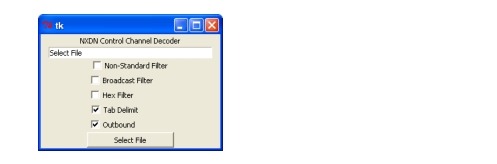
3. Unzip and launch the python script. The script file name is nxdn_ctrl_decoder.py.
4. Press the Select File button and select the control channel file that was saved on the USB flash drive. The Python script will display the CRC errors and write a text file in the same location with the decoded control channel commands.
 The script file name is nxdn_ctrl_decoder.py.