Use the MA25200A High Power Tx/Rx Input Protection Module to safeguard the S412E input ports from high power transmitters. The MA25200A attenuates RF power levels up to +51 dBm (125 W) to safe levels for measurements. The MA25200A connects directly to the RF input connector. It has an N(m) coaxial input cable that connects to the Signal Generator output. The top N(f) connector can be connected directly to portable or mobile antenna ports or base station transmit or receive ports. The nominal 40 dB insertion loss of the main input and signal generator ports can be compensated for in the S412E amplitude offset menus, enabling the displayed levels to match the RF levels at the input of the MA25200A. The insertion loss of the MA25200A is very flat over its frequency range of operation, supporting accurate amplitude measurements. Please see the MA25200A High Power Rx/Tx Input Protection Module Technical Data Sheet for specifications.
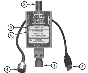
3. USB Type A - connect to the instrument to supply power for the cooling fan, LED indicators, and warning alarm.
4. Signal Generator Input N(m) - connect to instrument signal generator.
5. Green LED - indicates proper operation.
6. Red LED - indicates a fault or over temperature condition.
Caution
When the internal temperature exceeds 100 °C, the red LED illuminates and an internal piezo alarm sounds continuously until the temperature returns to the proper operating range. Stop testing immediately to prevent damage to the LMR analyzer or MA25200A module.