This instrument is equipped with Type N connectors. To prevent damage, do not use pliers or a plain wrench. Do not over tighten.
Recommended torque: 1.36 N·m to 1.70 N·m (12 lbf·in to 15 lbf·in).
Do not twist cable or accessory body. Rotate the coupling nut only.
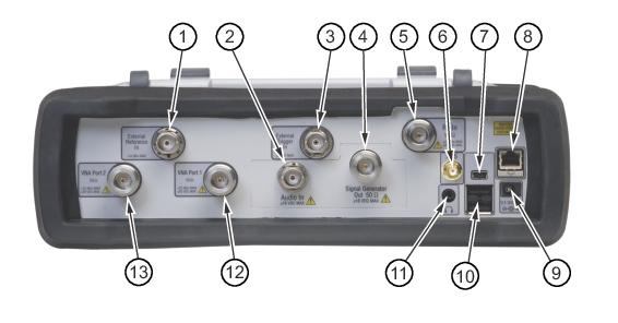
Test Panel Connectors
External Power
The external power connector (item 9 in Figure: Test Panel Connectors) is used to power the unit and charge the battery. Input is 12 VDC to 15 VDC at up to 5.0 A. The green flashing Power LED indicates that the instrument has external power.
Warning
When using the AC‑DC Adapter, always use a three‑wire power cable that is connected to a three‑wire power line outlet. If power is supplied without grounding the equipment in this manner, then the user is at risk of receiving a severe or fatal electric shock.
USB Interface – Type A
The LMR Master has two Type A USB connectors (item 10 in Figure: Test Panel Connectors) that accept USB Memory devices for storing measurements, setup data, screen images, and firmware updates.
USB Interface – Mini‑B
USB 2.0 Mini‑B connector (item 7 in Figure: Test Panel Connectors) can be used to connect the LMR Master directly to a PC. The first time the LMR Master is connected to a PC, the normal USB device detection by the computer operating system will take place. The CD‑ROM that is shipped with the instrument contains a driver for Windows XP that is installed when Master Software Tools is installed. Drivers are not available for earlier versions of the Windows operating system. During the driver installation process, place the CD‑ROM in the computer drive and specify that the installation wizard should search the CD‑ROM for the driver.
Note
For proper detection, either Line Sweep Tools or Master Software Tools should be installed on the PC prior to connecting the LMR Master to the USB port.
LAN Connection
The RJ‑45 connector (item 8 in Figure: Test Panel Connectors) is used to connect the LMR Master to a local area network or directly to a PC with an Ethernet crossover cable. Integrated into this connector are two LEDs. The amber LED shows the presence of a 10 Mbit/s LAN connection when on, and a 100 Mbit/s LAN connection when off. The green LED flashes to show that LAN traffic is present. For additional information about the LAN connection, Ethernet connection, and DHCP, refer to Ethernet Connectivity.
Headset Jack
The headset jack provides audio output from the built‑in AM/FM/SSB demodulator for testing and troubleshooting wireless communication systems. The jack accepts a 3.5 mm (1/8 inch) 3‑wire miniature phone plug such as those commonly used with audio headsets (item 11 in Figure: Test Panel Connectors).
External Trigger In
A TTL signal that is applied to the External Trigger In female BNC input connector causes a single sweep to occur. In the Spectrum Analyzer mode, it is used in zero span, and triggering occurs on the rising edge of the signal. After the sweep is complete, the resultant trace is displayed until the next trigger signal arrives (item 3 in Figure: Test Panel Connectors).
External Reference In
The BNC female connector (item 1 in Figure: Test Panel Connectors) is used for connection of an external frequency reference. The amplitude of the External Reference should be between – 10 dBm and + 10 dBm.
RF In (50 ohm)
This connector (item 5 in Figure: Test Panel Connectors) provides the input 50 ohm interface for the Spectrum Analyzer function. With Option 10, Bias Tee, output is available on the center pin out of this port in Spectrum Analyzer mode.
Audio In (item 2 in Figure: Test Panel Connectors) is used to support SINAD and Quieting measurements of analog FM radio sensitivity.
Signal Generator Out
Output of the built-in Signal Generator when the LMR Master is in CW, NBFM, P25/P25p2, NXDN, dPMR, DMR, TETRA, PTC-ITCR or PTC-ACSES mode (item 4 in Figure: Test Panel Connectors). Output is turned on with the Turn Sig-Gen ON main menu key.
VNA Port‑1 (50 ohm)
This connector (item 12 in Figure: Test Panel Connectors) provides the input/output 50 ohm interface for reflection measurements of the Vector Network Analyzer at Port 1.
VNA Port‑2 (50 ohm)
This connector (item 13 in Figure: Test Panel Connectors) provides the input 50 ohm interface for transmission measurements of the Vector Network Analyzer at Port 2. With Option 10, Bias Tee, output is available on the center pin out of this port in VNA mode.