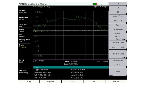
Carrier to Interference Ratio (C/I) Measurement is a two‑step process, first measuring the carrier level and then, with the carrier turned off, measuring the remaining signals and noise in the band of interest. After the two measurements are complete, the ratio of the carrier level to the noise plus interference is displayed using three assumptions:
• The interferer is a narrowband frequency hopping signal (NB FHSS)
• The interferer is a wideband frequency hopping signal (WB FHSS)
• The interferer is a broadband signal (BB).
The primary application for this type of measurement is determining the magnitude of interference problems for 802.11b, 802.11g and 802.11a access points (hot spots).
Procedure
1. Press the Freq main menu key followed by the Signal Standard submenu key. Select the appropriate signal standard based on the signal to be measured and press Enter.
2. Press the Channel submenu key, select the operating channel of the access point being measured and press Enter.
3. Press the Shift key followed by the Measure (4) key. Then press the Masks and C/I submenu key, and then the C/I submenu key.
4. Press the Center Freq (or Offset Center Freq) submenu key and enter the desired frequency, unless a Signal Standard and Channel have already been selected in the Frequency menu.
5. If needed, press the Span submenu key and set an appropriate span width for the signal to be measured.
6. If the signal environment includes slow frequency hopping signals, such as cordless telephones, press the Sweep Time submenu key to set a sweep time of one second or more to give a good chance of capturing instances of the interfering signal. The minimum sweep time for a valid measurement is displayed in the Min Sweep Time submenu key.
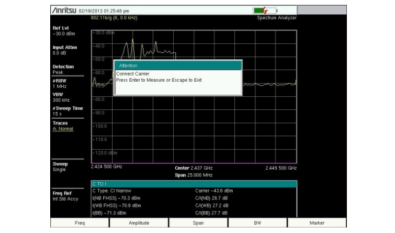
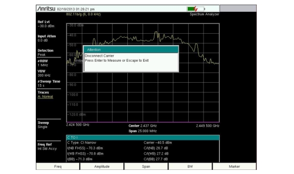
7. Press the On/Off submenu key and follow the on‑screen prompts to complete the measurement.
Note
Access to the transmitter is required to complete this procedure as the transmitted carrier must be turned off for the second portion of the measurement.
8. After the measurement is complete, the measurement box gives results for the three different signal types. Some measurement results may show as Error, and this is to be expected.