Firmware in both the MA24105A Inline Peak Power Sensor and in Option 19 interact to provide additional functions in the connected Anritsu handheld instrument. The firmware for the High Accuracy Power Meter (Option 19) and the firmware of your instrument must be up‑to‑date versions. Refer to Required Equipment.
Main Menu Keys
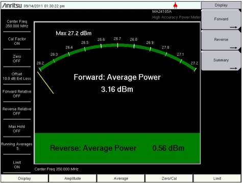
When the MA24105A is connected to your Anritsu handheld instrument with Option 19 installed, the five main menu keys are displayed at the bottom of the measurement display.
Display, Amplitude, Average, Zero/Cal, and Limit Keys
Connect the MA24105A to the Anritsu handheld instrument with Option 19.
1. Connect the USB cable between the sensor and your instrument. The MA24105A green power light is illuminated when power is available via the USB cable (refer to Figure: MA24105A Inline Peak Power Sensor).
2. Press the On/Off key to turn on your instrument.
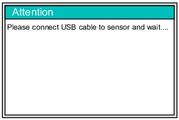
3. If the instrument is already On when the sensor USB cable is connected, an Attention message is displayed. Refer to Figure: USB Connection Message.
USB Connection Message
4. When the Attention message box is no longer displayed, the connection is enabled.