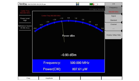
3. Press the Freq menu key to set the desired frequency.
CW Signal Generator Frequency Menu
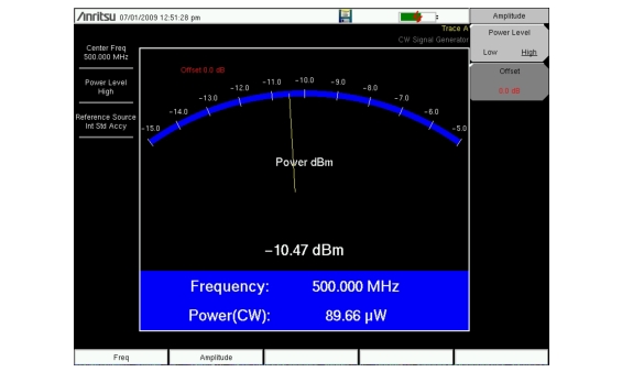
4. Press the Amplitude key and set the power level to High or Low. The typical nominal output power in the high setting is about 0 dBm. The typical nominal output power in the low setting is about –30 dBm.
CW Signal Generator Frequency Menu
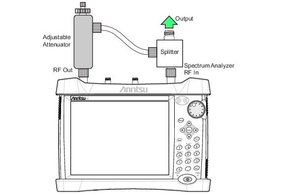
5. Change the settings on the attenuator to adjust the power level. The large knob changes the power in 10 dB steps and the small knob adjusts the power level in 1 dB steps.
6. Press the Offset submenu key to add an offset (in dB) to the amplitude level. This offset compensates for any attenuation that is placed in‑line between the splitter and the DUT. Offset range is +100 dB to –100 dB.