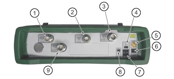
The External Reference In port is a 50 Ω BNC female connector that provides for input of an external frequency reference. Refer to your Technical Data Sheet for valid frequencies. To prevent damage to your instrument, do not use pliers or a wrench to tighten the BNC connector.
External Trigger In
A TTL signal that is applied to the External Trigger female BNC input connector causes a single sweep to occur. In the Spectrum Analyzer mode, it is used in zero span, and triggering occurs on the rising edge of the signal. After the sweep is complete, the resultant trace is displayed until the next trigger signal arrives.
Analyzer/RF In
This is a 50 Ω Type-N female connector. The maximum input is +33 dBm at ±50 VDC.
USB Interface – Mini-B
The USB 2.0 Mini-B connector can be used to connect the Spectrum Master directly to a PC. The first time the Spectrum Master is connected to a PC, the normal USB device detection by the computer operating system will take place.
Note
For proper detection, the applicable Anritsu Software Tool should be installed on the PC prior to connecting the Spectrum Master to the USB port.
GPS Antenna Connector (Option 31)
The GPS antenna connection on the Spectrum Master is type SMA-female. GPS function is described in GPS (Option 31).
To prevent damage to your instrument, do not use pliers or a plain wrench to tighten the SMA connector. Do not over-tighten the connector. The recommended torque is 8 lbf · in (0.9 N · m or 90 N · cm).
External Power
This is a 2.1 mm by 5.5 mm barrel connector, 12 to 15 VDC, < 4.0 A. The external power connector is used to power the unit and for battery charging. A green blinking LED near the Power button indicates that the instrument battery is being charged by the external charging unit. The indicator is a steady green when the battery is fully charged.
Warning
When using the AC-DC Adapter, always use a three-wire power cable that is connected to a three-wire power line outlet. If power is supplied without grounding the equipment in this manner, the user is at risk of receiving a severe or fatal electric shock.
The Spectrum Master has two Type A USB connectors that accept USB Flash Memory devices for storing measurements, setup data, and screen images.
Headset Jack
The headset jack provides audio output from the built-in AM/FM/SSB demodulator for testing and troubleshooting wireless communication systems. The jack accepts a 3.5 mm 3-wire miniature phone plug such as those commonly used with cellular telephones.
Generator/RF Out (Option 20)
RF output, 50 Ω impedance, for tracking generator (Option 20). The maximum input is +23 dBm at ±50 VDC.